3-8
Section 3 - Service and Repair
ICE MAKER OPERATING CYCLES
(U-CO29F MODEL)
Note:
The refrigeration system operates independently of the ice
maker. This is a new design for U-Line. All other U-Line ice makers
use a double throw control system where the unit is either in a
freeze mode or harvest mode. In the U-CO29FF, the refrigeration
system will cycle on and off depending on the temperature of the
freezer. In most cases, this means the refrigeration system will be
operating during the ice making and harvest modes. If the freezer
control is set too warm, the refrigeration system may cycle off during
ice making mode, slowing the ice production rate. If this happens,
adjust the freezer control colder.
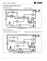
Freeze Cycle
• Ice maker thermostat (located behind grille) open.
• Freezer control closed and refrigeration system is operating.
Harvest Cycle - 1
• Ice maker thermostat closed.
• Refrigeration system operating.
• If bin arm is up, the harvest will not initiate.
• Power goes through the bin switch to the ice maker motor and
mold heater.
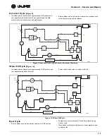
Harvest Cycle - 2
• Ice maker ejector blades reach 2:00 position and cam depresses
the hold switch.
• Ejector blades stall on ice and ice maker motor pulsates until
mold heater warms and ice releases.
• Refrigeration system operating.
Water Fill Cycle
• Ice maker blades reach approximately 10:00 position and cam
depresses the water fill switch.
• Power to the water valve. Ice maker mold fills.
• Refrigeration system operating.
Eject Cycle
• Ejector blades push ice into bucket and stop at 12:00 position.
• Ice maker temperature control opens.
• Refrigeration system still operating.
Содержание BI95FCB
Страница 9: ...1 8 Section 1 General Information This page intentionally left blank...
Страница 27: ...3 12 Section 3 Service and Repair THIS PAGE INTENTIONALLY LEFT BLANK...
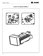
Страница 29: ...4 2 Section 4 Parts U LINE ICE MAKER ASSEMBLY...
Страница 61: ...4 34 Section 4 Parts This page intentionally left blank...
Страница 63: ...5 2 Section 5 Wiring Diagrams U CO29A CO1175A BI2115 ADA15IM 115 VOLT ULN 29R 115 VOLT...
Страница 64: ...5 3 Section 5 Wiring Diagrams 1075BEV 1075WC 115 VOLT...
Страница 65: ...5 4 Section 5 Wiring Diagrams ULN 95 ULN 98 SP18 22 1095 220 VOLT CO 29A CO1175 BI2115 ADA15IM 220 VOLT...


