EVK-M8L User Guide
UBX-20028627 - R01
Device description
Page 7 of 33
C1-Public
3
Device description
3.1
Interface connection and measurement
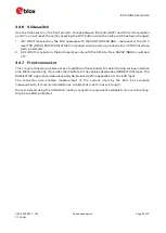
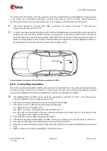
To connect the EVK to a PC, use a standard SUBD-9 cable and the included USB cable. The use of
RS232 and external power supply is optional. USB provides both power and a communication
channel.
Connect the wheel tick and forward/reverse signals as well as vehicle ground (GNDA) to the front
connector.
Figure 1: Connecting the unit for power supply and communication
3.2
Active antenna
The EVK-M8L evaluation kit includes a GPS / Galileo / GLONASS / BeiDou antenna with a 3-meter
cable. It is possible to connect various active and passive GNSS antennas with SMA connectors to
the evaluation unit.
The recommended maximum antenna supply current for active antennas is 30 mA.
3.3
Evaluation unit
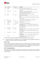
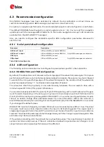
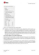
Figure 2 shows the front and the rear panel of the EVK-M8L evaluation unit.
Front panel
Rear panel
Figure 2: EVK-M8L evaluation unit – front and rear panels
3.3.1
Antenna connector
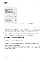
An SMA female jack is available on the front side (see Figure 2) of the evaluation unit for connecting
an active or passive antenna. The EVK provides a DC supply at the RF input of 3.3 V for active
antennas. The maximum supported antenna current is 30 mA; internal protection limits the
maximum short circuit current to 60 mA.
To avoid the damage of RF input caused by ESD or Electrical Overstress, and to seek maximum
consistency and repeatability of performance independently of the RF component used, the EVK-
M8L has an onboard LNA.


