EVK-M8L User Guide
UBX-20028627 - R01
Setting up
Page 12 of 33
C1-Public
4
Setting up
4.1
Test vehicle preparation
The test vehicle should allow easy installation. A practical vehicle for testing purposes is a hatchback
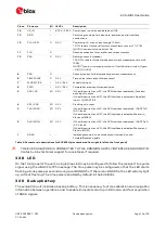
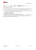
passenger car. The EVK relies on WHEELTICK and FWD signals from the vehicle as an essential
major part of its dead reckoning functionality. The characteristics of the signal inputs are specified
in Table 4 (HW interface).
Alternatively, if you have access to the proprietary CAN messages of the vehicle, the same
information may be delivered as UBX-ESF-MEAS messages on a communication port (SW interface).
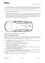
Note that EVK-M8L default configuration is set to HW input signals. Should UBX-ESF-MEAS
messages be used to input WHEELTICK and FWD information instead of HW signals, a change in
the configuration is required using UBX-CFG-ESFWT.
☞
More information on the SW interface can be found in the u-blox 8 / u-blox M8 Receiver
Description including Protocol Specification [5], or contact u-blox technical support for further
SW interfacing solutions.
The next sections focus on use of the HW interface.
The WHEELTICK signal:
Shall be representative of the distance traveled by the vehicle’s reference point. The reference
point is the mid-rear axle of the vehicle. Wheel ticks from the front wheels may be used as an
alternative with some compromise in performance.
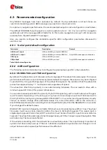
Shall be a series of (absolute wheel tick) pulses with one pulse corresponding to less than 0.4
meters of distance traveled. For best results one pulse should correspond to about one
centimeter of distance traveled.
Shall be available regardless of the direction of driving.
Shall be adequately de-bounced before application to the EVK input.
The FWD signal:
Shall indicate the direction of driving, i.e. forward or reverse.
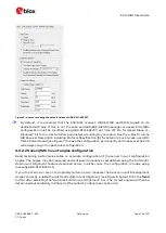
May have either polarity. By default the polarity will be detected automatically in normal use, but
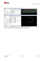
can also be configured explicitly with UBX-CFG-ESFWT command (see Figure 5).
May indicate either forward or reverse when the vehicle is stationary.
Most cars since 1980 provide a vehicle speed sensor (VSS) signal, which, for example, may be
available on the OBD/OBD-II connector as a signal or CAN message. For evaluation purposes, you can
use a device which converts the CAN messages to hardware WHEELTICK signals (see section 4.1).
The VSS and forward/reverse signals are also often available directly on standard Head Unit
connectors. If necessary, consult the vehicle service manuals, head unit installation manuals for the
vehicle, or a certified automotive electrician.
If the vehicle does not provide the signals readily, you can use external sensors as described in
section 4.1.3 below.
4.1.1
Wiring harness of the Head Unit
Remove the Head Unit (make sure you know the possible re-activation pass code). Locate the wheel-
tick and forward/reverse signals (check voltage and polarity).


