EVK-M8L User Guide
UBX-20028627 - R01
Setting up
Page 16 of 33
C1-Public
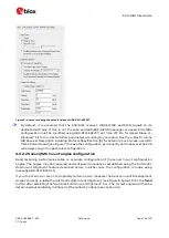
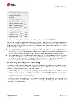
Figure 5: u-center showing the default values of UBX-CFG-ESFWT
☞
By default, it is assumed that the EVK-M8L receives WHEELTICK and FWD signals on its
dedicated HW pins. If this is not the case and UBX-ESF-MEAS messages are used, EVK-M8L
configuration must be modified using UBX-CFG-ESFWT: set “Use WT Pin for Speed Meas. (L-
Modules)” bit to 0 and set all other parameters according to your setup. See the u-blox 8 / u-blox
M8 Receiver Description including Protocol Specification [5] for details. In such a case, use UBX-
CFG-CFG command (see Figure 7) to save the configuration permanently and make sure the EVK
will always stay in this particular configuration.
4.3.2.2
Sensor/IMU mount angles configuration
Dead reckoning performance relies on accurate configuration of the sensor mount configuration
angles. The angles may be measured and configured manually or established using the Automatic
IMU-mount Alignment feature described below. In either case the configuration is made using
message UBX-CFG-ESFALG.
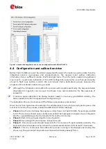
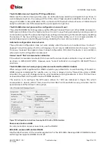
If you do not know or are not completely certain how to measure the Sensor-mount Misalignment
Angles correctly, enable the Automatic IMU-mount Alignment (see Figure 6 below). Click the Send
button after selelcting the “Automatic IMU-mount Alignment” box. The correct angles will then be
determined automatically in Phase II of the calibration drive (see section 4.4).

