background image


C099-F9P - User Guide 

UBX-18055649 - R02 

Reference station and rover pairing


Page 22 of 48 

6


Reference station and rover pairing 

This section is provided for users with two C099 boards and provides configuration information when 
setting up a C099-F9P as a reference station to provide local RTCM corrections for a C099 rover.  This 
connection uses Wi-Fi connectivity to maximize range for untethered operation. 

6.1


Wi-Fi connection between two C099-F9P boards 

This set-up relies on establishing a peer-to-peer Wi-Fi connection between two C099 boards for short 
base-line applications, e.g. drones and the like. 

Separate ODIN-W2 configuration files are required to enable the reference station and rover C099 
boards to operate as an Access Point and client respectively. 

Prior to use, the reference station C099-F9P needs RTCM3 output messages enabled and its position 
surveyed-in. When  the  device  is  surveyed-in it will  enable  output  of the RTCM3 1005 message to 
enable the rover to begin RTK operation.  Consult the Integration manual [4] for information relating 
to reference station operation for more information. 

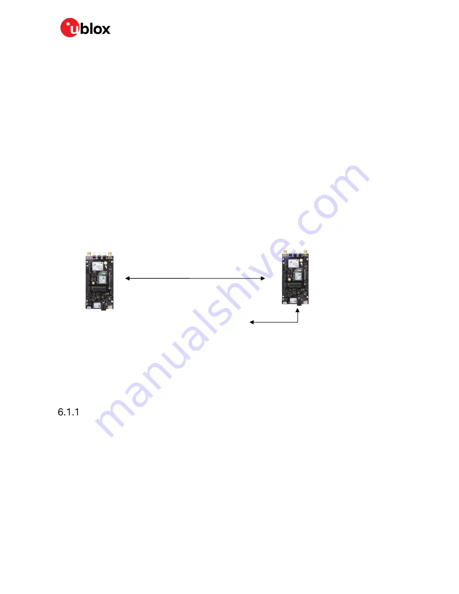
In this example the C099 reference station sends corrections to a C099 rover and the rover transmits 
NMEA and UBX messages back to the base. The rover operation can be viewed remotely with u-center 
connected to the reference station’s ODIN-W2 COM port. 


Figure 28: Reference and rover C099-F9P set up. 


The sub-sections below describe the steps required to configure the boards for Wi-Fi operation plus 
the settings needed for rover and base operation. 


Configuring a C099-F9P rover for Wi-Fi operation 

The following steps provide guidance on configuring the C099 ODIN-W2 Wi-Fi for rover operation: 


Disconnect any UART multiplexor jumper connections before proceeding. 


Connect the rover unit via USB to a PC.  


Install the u-blox s-center evaluation application. 


Open s-center which will show the following view: 

Bidirectional peer to peer Wi-Fi link 

Rover 

    Base 

USB #1 ODIN-W2 port to u-center 
for Rover data 

Содержание C099-F9P

Страница 1: ...ard enables customers to evaluate RTK operation with the ZED F9P high precision GNSS receiver The board provides short range wireless connection via Bluetooth or Wi Fi for receiving correction data an...

Страница 2: ...may hold intellectual property rights in the products names logos and designs included in this document Copying reproduction modification or disclosure to third parties of this document or any part t...

Страница 3: ...header connections 19 5 Rover operation using NTRIP 20 5 1 PC hosting via u center 20 5 2 Mobile hosting 21 5 3 Pairing the host with the C099 F9P 21 6 Reference station and rover pairing 22 6 1 Wi F...

Страница 4: ...tents Page 4 of 48 E 2 1 Patch antenna element specification 37 E 2 2 LNA electrical specification 38 E 2 3 Overall performance 38 F Mechanical board dimensions 39 G C099 F9P schematics 40 Related doc...

Страница 5: ...This makes it possible to stream in RTCM corrections while sending back logged data using u center evaluation software 3 There is an option to use two C099 F9P boards together one as a reference stati...

Страница 6: ...ZED F9P Interface Description Doc No UBX 18010854 Download u center https www u blox com en product u center windows and the u center User Guide https www u blox com sites default files u center_User...

Страница 7: ...r should begin operation in its default state The Figure 4 below shows a typical u center view with active satellite signal levels etc The TP LED on the C099 F9P board will blink in blue color To oper...

Страница 8: ...ervice In the Data View of u center the Fix Mode should change from 3D to 3D DGNSS when RTCM corrections are received The RTK LED will blink in green color Eventually the status will change to 3D DGNS...

Страница 9: ...The board can be powered by USB a DC supply socket or from a LiPo lithium polymer battery The board has been designed using an Arduino form factor with the modules serial ports routed to the shield h...

Страница 10: ...igure 5 Main components and USB ports J9 J8 J3 J2 ZED F9P Multi band GNSS RTK module ODIN W2 Multi radio module USB ZED F9P USB and UART ODIN W2 UART ports GNSS antenna connector J2 J3 J8 J9 Arduino U...

Страница 11: ...atus LED provides an indication of the state of the ZED F9P module RTK STAT pin At start up the LED is off When in RTK Float mode the yellow LED flashes at the navigation rate 1Hz default This is also...

Страница 12: ...colored LED to show particular activity status This is positioned adjacent to the ZED F9P reset switch and shown below in Figure 8 The activity status is summarized in Table 1 below Mode Status LED c...

Страница 13: ...rce via a 2 1mm connector center pin V Figure 9 Power connections Figure 10 Typical single cell 3 7V LiPo battery with JST connector Follow all published safety advice for using bare cell LiPo batteri...

Страница 14: ...to prevent any potential shorting of the antenna bias Figure 12 GNSS antenna connector When using the supplied antenna it is advisable to use the ground plane provided Otherwise ensure that there is a...

Страница 15: ...mbering can be different between individual PCs but the same arrangement applies Figure 14 Windows device manager COM port view In addition a third VCP will be created corresponding to the ZED F9P USB...

Страница 16: ...i Fi Bluetooth antenna has been connected to the SMA connector ODIN RF to ensure correct operation of the wireless functions The C099 F9P board is delivered with the ODIN W2 pre configured for connect...

Страница 17: ...The ODIN W2 module communicates with the ZED F9P via a serial port which is shared with the FTDI USB COM port via multiplexors Once Bluetooth communication is established with the ODIN W2 a jumper con...

Страница 18: ...ng or applications not connecting to the Bluetooth Virtual COM port In other cases Windows might crash or become un responsive This is not related to the ODIN W2 Bluetooth implementation that uses the...

Страница 19: ...o R3 Uno mechanical specification The functions of each I O align as much as possible to the Arduino specified functions Check the pin functions before using with an Arduino R3 Uno see Figure 23 below...

Страница 20: ...F9P 5 1 PC hosting via u center The u center application includes an NTRIP client for PC hosting The u center user guide 3 provides help when setting NTRIP service connections Users can connect via Bl...

Страница 21: ...own below is by Lefebure which is available from the Google play store It works with the C099 via Bluetooth other similar applications exist as well https play google com store apps details id com lef...

Страница 22: ...in it will enable output of the RTCM3 1005 message to enable the rover to begin RTK operation Consult the Integration manual 4 for information relating to reference station operation for more informat...

Страница 23: ...setting window Select the COM port installed for the ODIN W2 Set the baud rate to 460800 baud Ensure there is no hardware flow control enabled Click on the FTDI USB Latency Timer Update button Click...

Страница 24: ...This needs to be changed to no hardware flow control First set s center to 115200 baud and no flow control Then open the port Click EVK ODIN W2 via ST LINK button as shown below to disable flow contr...

Страница 25: ...isibility conditions Configuring a C099 reference station for Wi Fi operation The following steps describe setting up the C099 ODIN W2 Wi Fi for reference station operation Disconnect any jumper conne...

Страница 26: ...9P message data via the return Wi Fi link Connect the GNSS antenna ensuring use with the supplied ground plane and place in good GNSS visibility conditions A Wi Fi connection is established between re...

Страница 27: ...how to update the firmware and re enable the configuration settings required for the C099 To update the ZED F9P connect via USB to the COM port identified as the ZED F9P to u center and poll MON VER t...

Страница 28: ...and file Select the new firmware image bin file Figure 41 Selecting u center Firmware image file Set the Enter safeboot before update and Send training sequence options Set the Use this baudrate for u...

Страница 29: ...rogress and completion message When programming is complete the module will start up in a default configuration in which the ZED F9P serial port is set to 38400 baud This requires changing to 460800 b...

Страница 30: ...99 F9P is shipped with ODIN W2 FW5 0 standard connectivity firmware If there is a need to update the firmware then users should adopt the following process Carefully follow the series of steps of the...

Страница 31: ...ud rate to 460800 baud Ensure there is no hardware flow control enabled Click on the FTDI USB Latency Timer Update button Click Open Port The ODIN W2 should respond with AT commands in the Console Win...

Страница 32: ...programming of firmware and exit when completed After this the device baud rate is set to 115200 with hardware flow control enabled This requires changing to No hardware flow control First set up s c...

Страница 33: ...W2 UART will now be set to 460800 baud in Data default mode It will be ready for use again Disconnect s center from the ODIN W2 port and power the C099 F9P off and on to ensure it will be using the ne...

Страница 34: ...ine and place it in a text file named u blox ODIN W2 BT Rover txt AT UBTLN ODIN W2 xxxx AT UBTLC 000000 AT UBTCM 2 AT UBTDM 3 AT UBTPM 2 AT UBTMSP 1 AT UBTLE 0 AT UBTSM 1 AT UNHN ODIN W2 2000360015513...

Страница 35: ...000 AT UBTLECFG 22 5000 AT UBTLECFG 23 48 AT UBTLECFG 24 48 AT UBTLECFG 25 0 AT UMSM 1 AT UMRS 460800 2 8 1 1 1 AT W AT CPWROFF C Rover ODIN W2 Access Point UDP Server txt Copy all the text below this...

Страница 36: ...uetooth antenna specification EX IT WLAN RPSMA Ex IT WLAN SMA Manufacturer ProAnt Type wave dipole dual band antenna Polarization Vertical Gain 3 dBi Impedance 50 Size 107 mm straight Type Monopole Co...

Страница 37: ...band GNSS antenna specification This section details the u blox multi band GNSS antenna specification and performance on the required ground plane Figure 55 u blox dual band GNSS antenna E 2 1 Patch...

Страница 38: ...099 F9P User Guide UBX 18055649 R02 Appendix Page 38 of 48 E 2 2 LNA electrical specification Figure 57 LNA specification E 2 3 Overall performance Figure 58 u blox multi band GNSS antenna performance...

Страница 39: ...C099 F9P User Guide UBX 18055649 R02 Appendix Page 39 of 48 F Mechanical board dimensions Figure 59 C099 F9P rev B dimensions...

Страница 40: ...C099 F9P User Guide UBX 18055649 R02 Appendix Page 40 of 48 G C099 F9P schematics The following pages show the complete schematic for the C099 F9P evaluation board...

Страница 41: ...C099 F9P User Guide UBX 18055649 R02 Appendix Page 41 of 48...

Страница 42: ...C099 F9P User Guide UBX 18055649 R02 Appendix Page 42 of 48...

Страница 43: ...C099 F9P User Guide UBX 18055649 R02 Appendix Page 43 of 48...

Страница 44: ...C099 F9P User Guide UBX 18055649 R02 Appendix Page 44 of 48...

Страница 45: ...C099 F9P User Guide UBX 18055649 R02 Appendix Page 45 of 48...

Страница 46: ...C099 F9P User Guide UBX 18055649 R02 Appendix Page 46 of 48...

Страница 47: ...c No UBX 18010854 3 u center User Guide Doc No UBX 13005250 4 ZED F9P Integration Manual Doc No UBX 18010802 For regular updates to u blox documentation and to receive product change notifications reg...

Страница 48: ...ffice China Beijing Phone 86 10 68 133 545 E mail info_cn u blox com Support support_cn u blox com Regional Office China Chongqing Phone 86 23 6815 1588 E mail info_cn u blox com Support support_cn u...

Отзывы: