►
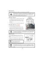
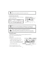
Independent PTO
PTO monitor Lamp
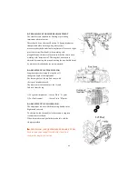
Two switches operate the independent PTO.
1.PTO ON/OFF switch: PTO ON/OFF switch is situated
■
It must be noted that the PTO shift lever on the LHS
below the driver seat should be shifted to position 1
(540 RPM) 0r 2 (1000RPM) depending upon the
implement specification. In no case the specified
speeds be crossed as serious damage to the
tractor/implement to person can result because of
this. When the PTO is not in use the shift lever must
be put in neutral position to avoid unnecessary use or
accidental use.
■
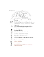
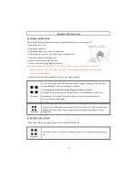
The PTO monitor lamp on the dash panel indicates the state of the PTO shaft.
1. If the monitor glows: The PTO is rotating
2. If the monitor is off: The PTO is off
3. If the monitor blinks: The PTO is presently stationary but will
instantly start rotating of the clutch pedal is released or the implement
is lowered
37
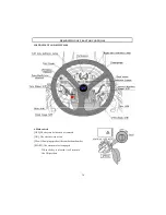
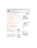
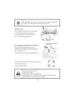
1.PTO ON/OFF switch: PTO ON/OFF switch is situated
on the LHS. on the steering column and can be identified
easily with its built in red colored indicator. When the
switch is pushed down to start the PTO indicator glows to
indicate that the switch and the PTO are in ON position,
If the switch is pushed down again the indicator goes off
signaling that the PTO is OFF.
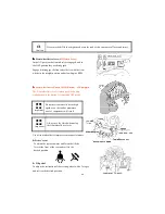
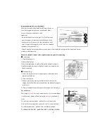
2. PTO Control switch: This switch is situated near the
starting key location on the dash panel. There are three
positions marked for this switch.
■
Off at the center
■
■
■
■
Manual at the left
■
■
■
■
Auto at the right.
PTO ON,Off switch
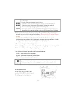
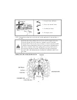
The PTO shaft will not rotate if either of the two switches is
in OFF position.
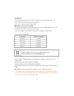
The following table explains how the PTO operates at the two
different (Manual & Auto) positions of the PTO control switch
with the PTO ON/OFF switch in the on position.
PTO control switch
Содержание T603
Страница 2: ......
Страница 34: ......
Страница 82: ......
Страница 105: ...T603 CABIN WIRING DIAGRAM A3 103 ...
Страница 106: ......
Страница 107: ...T603 ROPS WIRING DIAGRAM A3 105 ...
Страница 108: ......
Страница 109: ...T603 WIRING DIAGRAM FOR POWER SHUTTLE If equipped 105 ...
Страница 110: ......
Страница 111: ...WIRING DIAGRAM 107 ...
Страница 112: ...CABIN WIRING DIAGRAM 108 ...
Страница 113: ...CABIN WIRING DIAGRAM 109 ...
Страница 115: ... T603 POWER TRAIN 111 ...
Страница 116: ... T603 POWER TRAIN FOR POWER SHUTTLE If equipped 111 ...
Страница 117: ...DATE JOB CARD NO NATURE OF DEFECT PARTS REPLACEMENT W CLAIM NO AND DATE REMARK S TRACTOR HISTORY CARD 112 ...
Страница 118: ...DATE TRACTOR HOURS NATURE TYPE OF REPAIR SERVICE CARRIED OUT SERVICE RECORD 113 ...
Страница 119: ...DATE JOB DONE MACHINE HOURS FUEL CONSUMPTION ENGINE OIL TOPPED UP REMARKS START END DAILY OPERATION LOG 114 ...
Страница 120: ...PART REPLACEMENT RECORD DATE PART DESCRIPTION QTY COST DATE PART DESCRIPTION QTY COST 115 ...
Страница 121: ...T603 Operator s Manual for Tractors Code No 1995 940 002 1 Printed on August 2008 3rd Edition ...


