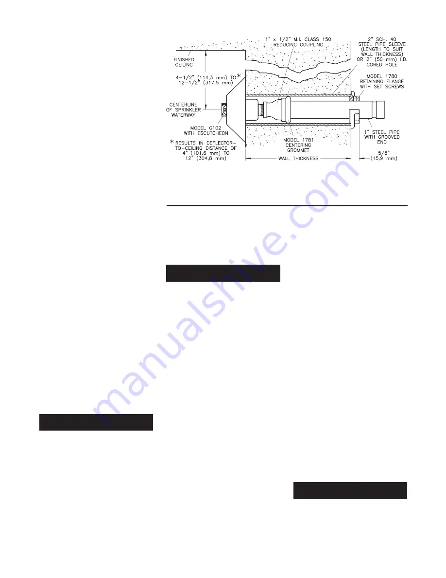
to ceiling distance of 4 to 12 inches
(100 to 300 mm). To meet this require-
ment the centerline of the sprinkler
waterway must be located 4-1/2 to 12-
1/2 inches (114,3 to 317,5 mm) below
the ceiling (Ref. Fig. C).
Only the Institutional Escutcheons
shown in Figure B can be utilized with
the Model G102, and only a maximum
of three Model 1752 Spacers can be
utilized with Type B1 or D Institutional
Escutcheons when horizontal adjust-
ment is desired.
NOTES
The Sprinkler Body must not extend
beyond the Institutional Escutcheon
(Ref. Fig. D). Otherwise the tamper
resistant design of the Model G102
will be compromised. Consequently, a
maximum of three Model 1752 Spac-
ers can only be used with Type B1 or
D Institutional Escutcheons. The
Model 1752 Spacers cannot be
utilized with the Type E Institu-
tional Escutcheons.
Integrity of the tamper resistant de-
sign of the Institutional Escutcheons
is dependent on the piping installa-
tion design. When installed properly,
the Institutional Escutcheon is held
fast to the mounting surface by the
tightening of the sprinkler assembly
into the sprinkler fitting. In order to
accomplish a proper installation, the
sprinkler fitting must be properly lo-
cated with respect to distance from the
face of the sprinkler fitting to the face
of the mounting surface (Ref. Fig. B);
the sprinkler fitting being rigidly se-
cured and held immobile; and, the
centerline of the sprinkler fitting be-
ing perpendicular to the mounting
surface to assure that the escutcheon
sits squarely against the mounting
surface around the entire perimeter of
the Institutional Escutcheon. Figure
C illustrates a typical installation
that can be utilized to help adjust the
location of the sprinkler fitting; to
help assure immobility of the sprin-
kler fitting; and, to help maintain per-
pendicularity of the sprinkler fitting
to the mounting surface.
OPERATION
In the standby condition, the design of
the Model G102 is such that a sus-
pended load of 75 lbs. (34 kg) or more
applied to the linkage mechanism will
release the sprinkler.
Also, when
properly installed, the escutcheon is
held fast to the wall to deter removal of
the escutcheon. The shape of the es-
cutcheon cannot easily be grasped,
which further deters tampering.
A glass bulb operating element is pro-
tected within the linkage mechanism of
the Model G102. The bulb contains a
fluid which expands when exposed to
heat. When the rated temperature is
reached, the fluid expands sufficiently
to shatter the glass bulb. Shattering of
the glass bulb releases the linkage
mechanism holding the sprinkler
closed, which then allows the sprinkler
to activate by allowing the deflector to
extend outward, and water to flow.
INSTALLATION
The 5.6 K-Factor, Model G102 Sprin-
klers must be installed in accordance
with the following instructions:
NOTES
Refer to the Design Criteria section for
important information regarding the
piping installation design and its ef-
fect on maintaining the integrity of
the tamper resistant design of the In-
stitutional Escutcheons.
If the bulb within the linkage mecha-
nism is cracked or there is a loss of
liquid from the bulb, do not install the
sprinkler. With the bulb in the hori-
zontal position, an air bubble of ap-
proximately 1/16 inch (1,6 mm) di-
ameter should be present.
A leak tight 1/2 inch NPT sprinkler
joint should be obtained with a torque
of 7 to 14 ft.lbs. (9,5 to 19,0 Nm). A
maximum of 21 ft.lbs. (28,5 Nm) of
torque is to be used to install these
sprinklers. Higher levels of torque
may distort the sprinkler inlet with
consequent leakage or impairment of
the sprinkler.
Do not attempt to compensate for im-
proper location of the sprinkler fitting
by under- or over-tightening the
sprinkler. Readjust the position of the
sprinkler fitting to suit, or increase or
decrease the number of Model 1752
Spacers, as applicable.
After the installation is complete,
make certain that the Institutional
Escutcheon is held fast to the mount-
ing surface and that it sits squarely
against the ceiling around its entire
perimeter.
1. The G102 Sprinklers must be in-
stalled horizontally with the center-
line of their waterway perpendicular
to the back wall surface, and the
Deflector must be located with the
top towards the ceiling (Ref. Figure
A).
2. With the Institutional Escutcheon in
place and with pipe thread sealant
applied to the pipe threads, hand
tighten the sprinkler into the sprin-
kler fitting.
3. Wrench tighten the Sprinkler using
only the Model 1509-1 or Model
1509-3 Sprinkler Wrench (Ref. Fig.
E). The wrenching teeth of the Sprin-
kler Wrench are to be applied to the
sprinkler wrenching notch areas
(Ref. Fig. A).
4
After the installation is complete,
make certain that the Institutional
Escutcheon is held fast to the
mounting surface and that it sits
squarely against the wall around its
entire perimeter.
NOTE
The Sprinkler Body must not ex-
tend beyond the Institutional Es-
cutcheon (Ref. Fig. D). Otherwise
the tamper resistant design of the
Model G102 will be compromised.
CARE AND MAINTENANCE
The 5.6 K-Factor, Model G102 Sprin-
klers must be maintained and serviced
in accordance with the following in-
structions:
NOTES
Service inspections should be made
FIGURE C
TYPICAL INSTALLATION WITH MODEL 1780 RETAINING FLANGE AND
MODEL 1781 CENTERING GROMMET
OBSOLETE


