


7;5;6\VWHPV,QF
Manual 7-9547-1 12/09/14 Page 39
The LAN connector on the front panel of the deck
provides for 10/100 BASE-T Ethernet connection
using the TCP-IP or DNS protocol. The control unit
deck is shipped from the factory with a default
TCP/IP address of “
192.168.1.1
”. A direct connec-
tion (at the installation site) should be established
the first time you interface to the SNMP feature
using the fixed IP mentioned above. Once the initial
communications are established the IP address in
the deck can be changed to permit a connection to
the internet. The initial direct connection should be
made with an Ethernet crossover cable.
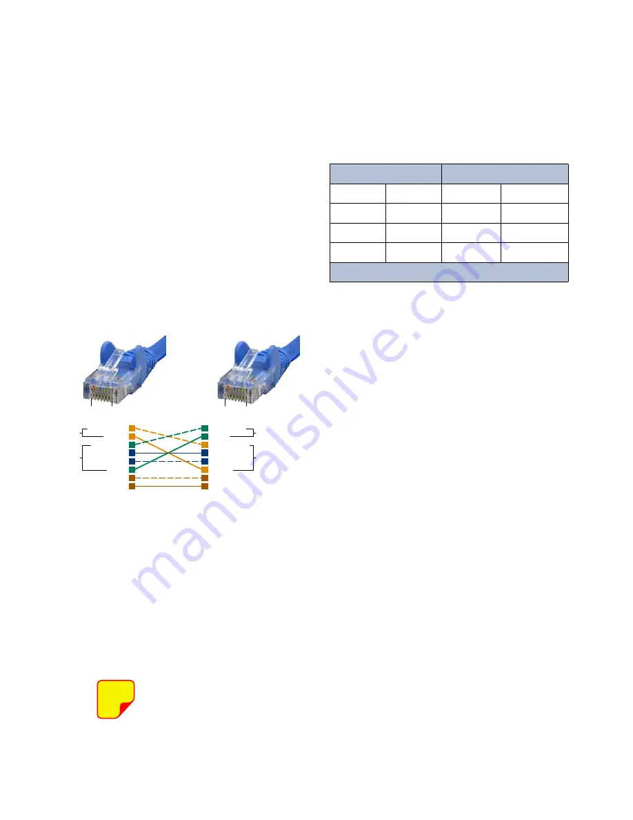
Figure A1
shows the pinout for a CAT-5 crossover cable.
Procedure
To direct connect your laptop computer to the LAN
port on the deck perform the following steps;
1) Connect your laptop network port to the LAN
connector on the deck using a standard CAT-5
Crossover cable.
The front panel LAN connector has
two built-in bi-color status LED’s
which will aid you in establishing
communications. The meaning of
each LED is shown in
Table A1
.
2) The left-most (LINK) status LED built-in to the
LAN port connector should illuminate amber or
green indicating that a good physical connec-
tion is established between your computer and
the TTA. After a few moments of initialization
the right-most LED should flash occasionally.
4) Insure that your laptop’s IP address is compati-
ble with the default address of the deck. This
may require changes be made to the Ethernet
adaptor address on your laptop (refer to
Appendix B
). Your laptop’s IP address will
need to be set to
“192.168.1.2”
along with a
subnet mask of
“255.255.255.0”
. The right-
most (ACTIVITY) status LED built-in to the LAN
port connector will turn amber or green and
flash occasionally indicating good TCP-IP com-
munications are established between the laptop
and the control unit.
5) Launch your web browser software on the lap-
top.
6) In your web browsers address box type-in the
IP address of the deck “http://192.168.1.1” and
press the ENTER button. The home screen
(System Summary) of the SNMP feature should
appear in your laptop’s browser window.
NOTE
APPENDIX A
Ethernet Connectivity
LINK LED
(left side)
ACTIVITY LED
(right side)
Color
Meaning
Color
Meaning
Off
No Link
Off
No Activity
Amber
10 Mbps
Amber
Half-Duplex
Green
100 Mbps
Green
Full-Duplex
Table A1
: LAN port status LED’s
1
4
7
6
3
5
8
2
1
4
7
6
3
5
8
2
Orange/White
Orange
Green/White
Blue
Blue/White
Green
Brown/White
Brown
Green/White
Green
Orange/White
Blue
Blue/White
Orange
Brown/White
Brown
Transmit (1 & 2)
Receive (3 & 6)
Transmit (3 & 6)
Receive (1& 2)
Pins 4, 5, 7 and 8 are not used
Pin
Pin
CAT-5 Cross-Over Cable
1
8
1
8
Figure A1:
CAT-5 Crossover cable pinout.
Содержание 434B-83H-01-M-110/48
Страница 12: ...7 5 6 VWHPV QF Manual 7 9547 1 12 09 14 Page 12 Figure 5 Functional block diagram of the system...
Страница 18: ...7 5 6 VWHPV QF Manual 7 9547 1 12 09 14 Page 18 Figure 9 Base Control Unit MCU system installation guidelines...
Страница 19: ...7 5 6 VWHPV QF Manual 7 9547 1 12 09 14 Page 19 Figure 10 System installation guideline notes...
Страница 44: ...8625 Industrial Parkway Angola NY 14006 Tel 716 549 4700 Fax 716 549 4772 sales W U com www W U com...


