TCF&B ES-52
3
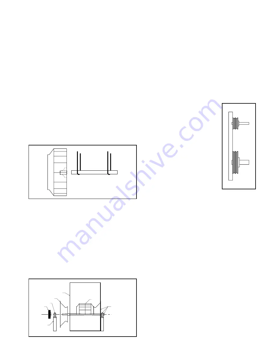
Figure 3. Drive Component Assembly
not touch clean areas of shaft with hands. Perspiration
can cause rust or pitting over time.
b. Remove keys from shaft.
c. Clean inside of wheel bore with solvent. Make sure set
screws will not interfere when inserting shaft into
wheel bore.
6. Arrangement 1, 9 or 10: Drive Component Assembly (See
Figure 3):
a. Insert shaft into wheel from back side of wheel.
b. When shaft is flush with wheel hub, put key into key-
way and tighten wheel set screws.
c. Insert shaft through opening in drive side. (If split
housed unit, lower into position.)
d. Install bearings onto shaft. Do not tighten bearing set
screws at this time. The bearing housing should be
perpendicular and the bearing base parallel to the axis
of the shaft to prevent loads caused by misalignment.
e. Mount assembly, bolt bearings to drive stand. Shaft
must be parallel with side of bearing pedestal. After
aligning and bolting bearings to pedestal, tighten
bearing set screws. Continue with step 8.
7. Arrangement 3 (Split-housed) units ( See Figure 4):
a. Parts on DWDI units are assembled in the following order
as viewed from opposite drive side: Bearing
bar assembly and opposite bearing, funnel, (housing
side), wheel, (housing side), funnel, drive side
bearing bar assembly, drive bearing and sheaves. Mount
bearing bar assembly to housing. Center wheel in funnels.
b. Parts on SWSI are assembled in the following order as
viewed from opposite drive side: Bearing bar assembly
and opposite bearing, funnel, (housing side), wheel,
(housing side), drive side bearing bar assembly, drive
bearing and sheaves. Mount bearing bar assembly to
housing. (See Figure 6 for wheel-funnel overlap.)
c. Assemble parts in above order on shaft.
Shaft
Centerline
Bearing
Pedestal
Sheave
Bearing
Inlet Funnel
Housing Side
Wheel
Assembled Bearing,
Shaft, Funnel, and
Housing. Frame
Angles Not Shown.
Figure 4. Split-housed Drive Component Assembly
d. Move assembly into position. Lightly bolt bearings
into place.
e. Shaft should be parallel with discharge of housing.
Move bearings to accommodate.
f. Level shaft; shim bearings if required. Tighten bearing
set screws.
8. Install motor on base. Carefully align shafts for drive
installation.
9. Mount drives as follows:
a. Slip (do not pound) proper sheave onto corresponding
shaft as close as possible to bearing. CAUTION:
PLACING FAN SHEAVE ON MOTOR CAN OVER-
SPEED WHEEL AND CAUSE STRUCTURAL FAIL-
URE.
b. Align sheaves with a straightedge
extended along perimeters of both
sheaves, just making contact in
two places on outside the perime-
ters of both sheaves (see Figure
5).
c. Tighten down sheave bolts.
d. Install a matched set of belts.
Slide the motor to obtain slack
and tighten belts. Using a pry
will damage belts.
e. Tighten belts to proper belt ten-
sion. Ideal tension is just
enough tension so that belts do
not slip under peak load.
Recheck sheave alignment.
f. After initial installation of belts,
recheck belt tension again after
a few days to adjust belt ten-
sion. (New belts require a break-
in period of operation.)
10. Install any safety devices or accessories supplied.
(Accessories commonly used are inlet vanes, shaft
seals and shaft coolers, plugs, dampers, and inlet or
discharge screens. Refer to appropriate documents in
appendix.)
11. Grout may now be applied. Grout is used to distribute
loads and should not be used as the sole support of
any rotating equipment.
12. When connecting the fan to the system, it is recom-
mended that the inlet and discharge be isolated from the
system with flex connections (where practical) to block
transmitted vibration. All duct connections to the fan
should be independently supported. Do not use fan to
support duct.
Fan Operation - Safety
For general safety practices for air moving equipment, see
AMCA Bulletin 410.
Twin City Fan & Blower has many safety accessories
available. These safety devices include (but are not limited
to) belt guards, shaft guards, inlet and discharge screens.
The use, abuse, or non-use of safety devices is the respon-
sibility of the purchaser.
Facility-related safety conditions include fan accessibility
and location. How easily can non-service personnel access
the unit? Is the fan in a hazardous duty environment? Was
the unit ordered for this duty? Other concerns must also be
addressed. All fans should be powered through switches
which are easily accessible to service personnel from the
Figure 5.
Sheave Alignment


