Chapter: H.3. Installation
H.3.3. Connecting the power circuit
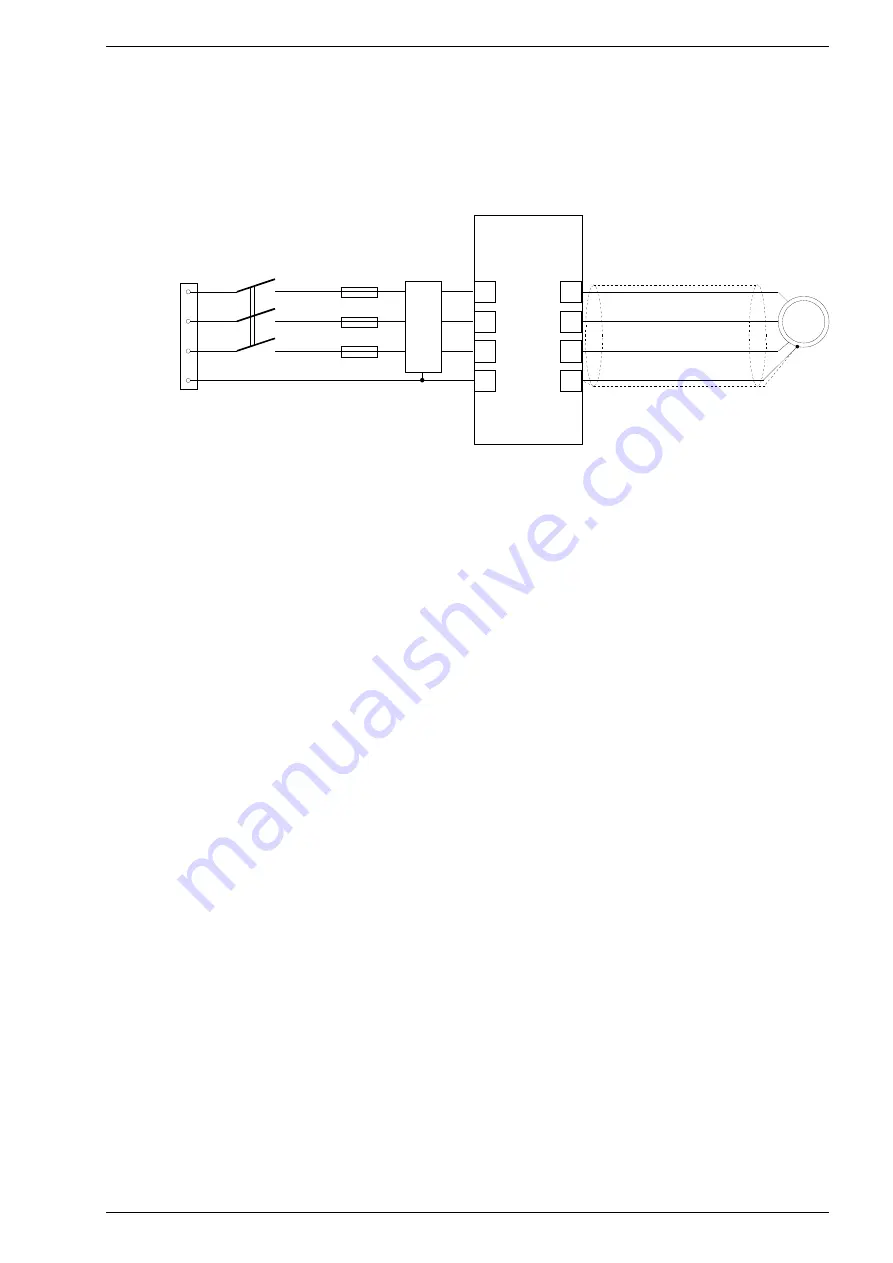
The frequency converter is powered by a three-phase power line through terminals L1, L2, L3. Information
about the supply voltage is also placed on the nameplate. Figure 3.1 shows the electric scheme of the power
circuit connections.
H.3.4. Using contactors between the frequency converter and the motor
If it is necessary to use contactors between the drive and the motor, make sure to switch the contactor when
there is no voltage on the output terminals and the drive is stopped (STOP status). Otherwise, there is a high
probability of damage to the drive.
CAUTION: just issuing the STOP command is not enough, because there is a possibility of programmatic
delay of the reaction to the STOP command (par. 13.20) and the possibility of setting the ramp stop (par.
11.20). For this reason, in order to avoid damage, it is necessary to check the operation status of the
converter (PCH514), e.g. by using one of the relays output K.
MFC1000AcR, TWERD Power Electronics
13
Fig. H.3.1. Example connections of the power circuit
MFC 1000 AcR
L1
L2
L3
Overcurrent
protection
Power switch
PE
L1
L2
L3
PE
U
V
W
PE
Shield cable recommended
Output voltage can be measured
correctly only with an electromagnetic
voltometer!
M
~
U
V
W
PE
NOTE!
Shown circuit has terminals for
illustration only and does not show their actually
position on the drive
L
in
e
p
o
w
er
s
u
p
p
ly
:
3
x
4
00
V
ac
o
r
3
x
6
90
V
ac
RFI


