background image

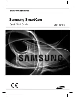
Calibration Procedure 

25 

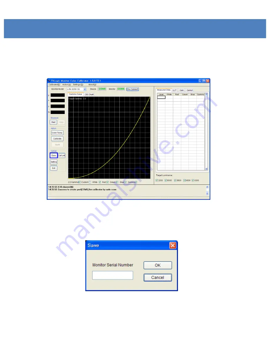
Saving the Calibration data


1. To save the calibration data, please click the “Save” button. 

Fig 6 Save calibration result


2. Input the Monitor’s serial number (or file name). 

Fig 7: Save file dialog


3. The File will be saved under the directory:  

“C:\Program Files\TvLogic\Calibrator\data”. 

Содержание XVM-175W

Страница 1: ...17 Multi Format LCD Monitor XVM 175W Multi Format LCD MONITOR Service Manual 1 ...

Страница 2: ...st a qualified person to perform servicing If any of the following conditions occurs unplug the power cord from the DC outlet and request a qualified service person to perform repairs a When the power cord or plug in damaged b When a liquid was spilled on the products or when objects have fallen into the products c When the products have been exposed to rain or water d When the products have been ...

Страница 3: ...Part Name Function 3 XVM 175W Front XVM 175W Rear ...

Страница 4: ...Drawing ...

Страница 5: ...Exploded View ...

Страница 6: ...I DIGITAL Video mode support resolution DVI DIGITAL Video mode support resolution DVI DIGITAL HDMI is divided into graphic and video mode DVI ANALOG DIGITAL HDMI mode when scan is not zero scan the picture may not be output properly When output image is not wide mode but aspect mode the image is output by pressing ASPECT button Resolution Frequency 640 480 60Hz 75Hz 800 600 60Hz 72Hz 75Hz 1024 768...

Страница 7: ...l HD SDI YPbPr RGB 4 4 4 1080i 50 59 94 60 1080p psf 30 29 97 25 24 23 98 SMPTE 274M 1080i 60 59 94 50 1080p 30 29 97 25 24 24sF 23 98 23 98sF SMPTE 296M 720p 60 59 94 50 SMPTE 260M 1035i 60 59 94 SMPTE 125M 480i 59 94 ITU R BT 656 576i 50 Audio In Embedded Audio Analog Stereo Phone Jack Audio Out Analog Stereo Phone Jack LCD SPEC Size 17 Resolution 1920 1080 Dot Pitch 0 199mm 0 199mm Color 10 bit...

Страница 8: ...PCB Block Diagram 8 ...

Страница 9: ...gnal at the same time After changing Digital signal into Analog one Audio AMP LM4849 amplifies audio then puts out Audio Out J16 SAMSUNG K4S641632H UC75 memory is used for 3D COM Serial Flash Memory is a device that saves images and loads them when they are needed CPU controls whole circuit Temperature sensor and keys are under CPU control Scaler Deinterlace have 4 of DDR save images and load them...

Страница 10: ...E ANALOG CHANNEL SDI A CHANNEL SDI B CHANNEL PBP CHANNEL TALLY R TALLY G UNDER SCAN 1 1 SCAN ASPECT H V DELAY BLUE ONLY MONO 16 9 MARKER 4 3 MARKER 4 3 ON AIR MARKER 15 9 MARKER 14 9 MARKER 13 9 MARKER 1 85 1 MARKER 2 35 1 MARKER 1 85 1 4 3 MARKER CENTER MARKER SAFETY AREA 80 SAFETY AREA 85 SAFETY AREA 88 SAFETY AREA 90 SAFETY AREA 93 SAFETY AREA 100 708 608 LINE21 608 ANC OP47 PIN 7 POWER ON OFF ...

Страница 11: ...ble with V1 0 and above Leave the monitor on 2 Upgrade program settings Run XVM_COMM exe Picture 1 Monitor upgrade SW Enter the same IP address as entered for the monitor See picture 2 Changing the PORT No is not recommended When the CON TEST button is pressed Version number will appear in the Ver Box if connected properly If not will appear in the box If appears check the IP address for the monit...

Страница 12: ...A 1 for DEV in UPDATE PROCESS Then press OPEN and select the FPGA firmware file Press the SEND button to start transferring the firmware file to the Ethernet Board Picture 3 Transfer finished message window Once the transfer finishes message window appears to confirm the start of update ...

Страница 13: ... to start transferring the firmware file to the Ethernet Board CPU Se lect ARM GEN for DEV in UPDATE PROCESS Then press OPEN and select the ARM GEN firmware file Press the SEND button to start transfer Follow the above FPGA updating steps to finish the update VXP Select VXP 1 for DEV in UPDATE PROCESS Then press OPEN and select the VXP firmware file Press the SEND button to start transfer Follow t...

Страница 14: ...of PC and RS232 port of monitor The PC must have RS232 port and can not use the USB to RS232 converter See Picture 7 for the cable connection Select COM PORT Select 14 7456MHz for TARGET CLK Select 2148B for MCU TYPE OPEN and select the mot file Press the SEND button 3 How to Upgrade ETHERNET BOARD ...

Страница 15: ...15 UPGRADE ETHERNET BOARD 2 RX 3 TX 4 DTR 5 GND 6 DSR 7 RTS 8 CTS 2 RX 3 TX 4 DTR 5 GND 6 DSR 7 RTS 8 CTS MONITOR RS232 MALE PC RS232 MALE 9 RI 9 RI Picture 7 Cable connection for ETHERNET BOARD upgrade ...

Страница 16: ...the CyUSB driver on your PC 2 Turn on the monitor after connecting the PC with monitor by USB Cable 3 Upgrade program settings Run LCD_PROG exe LCD_PROG exe 실행 Check the connection in PROGRAMMER STAUS Select AUTO UPDATE from check box ...

Страница 17: ...re update FPGA A B Picture 9 FPGA setting Select FPGA on PROGRAM STATUS Click FILE OPEN button as in FPGA A at BANK0 then you can load firmware as in FPGA A Click FILE OPEN button as in FPGA B at BANK1 then you can load firmware as in FPGA B Click on the DOWNLOAD button to start download ...

Страница 18: ...for CPU Click on DOWNLOAD button to start download Follow the FPGA updating steps to finish the update VXP Select the VXP check box in PROGRAM STATUS Select BANK0 from the bank selection window Then click on the FILE OPEN button to open the firmw are for VXP Click on the DOWNLOAD button to start downlo ad Follow the FPGA updating steps to finish the update FPGA A CPU and VXP should be separately u...

Страница 19: ...orSetup exe 1 2 Calibration Program Setup window will launch as shown below Click the Next button The calibration software requires these minimum hardware specifications CPU Pentium PC System Windows 98SE 2000 ME XP Display All compatible 24 bit Video Card Windows 98 2000 XP supporting 1024x768 resolution ...

Страница 20: ... user sees the image below the installation was successful 1 5 Copy the LicenseKey tvl file into the Program directory bin folder Ex C Program Files Tvlogic Calibrator Bin 1 3 When the Calibration Program Setup window loads click the Install button ...

Страница 21: ...able provided with the initial serial cable must be connected TX RX GND connector cable RS 232 USB Serial 2 Connect the measuring device and the PC with a serial cable or a USB Use an appropriate cable depending on the type of measuring device 3 When you connect to X Rite CA 210 CS 200 or Eye One please use a USB to connect the measuring device and the PC Device driver provided by the measuring de...

Страница 22: ... ports will be displayed on the top of the screen If the port s sign is highlighted in green the monitor and the probe is well connected If they are not connected the port s sign will be highlighted in red If they are not connected check the cable is correctly connected and attempt re connection by clicking the Re Connect button Fig 3 Status of a connected serial port LVM 182W ...

Страница 23: ...efore calibration 6 Click the Calibrate button Calibration takes around 20 30 minutes to complete Setting Calibration Gamma 2 2 Target Luminance 120 cd m2 Measurement steps 16 Backlight Backlight Stabilization Check Setting Device Measuring Device You can set the channel when using the K 10 probe If you did not add an adjusted channel in the K 10 probe you can use it without a channel change ...

Страница 24: ...bration Procedure 24 Fig 4 Monitor Calibration in process 7 A message stating Finish calibrating LCD Panel will be displayed if your calibration procedure was successful Fig 5 Calibration completion window ...

Страница 25: ...ata 1 To save the calibration data please click the Save button Fig 6 Save calibration result 2 Input the Monitor s serial number or file name Fig 7 Save file dialog 3 The File will be saved under the directory C Program Files TvLogic Calibrator data ...

Страница 26: ...election and other settings needed for Calibration Calibration Tab Fig 8 Calibration Settings dialog Gamma The default Gamma setting is 2 2 If required the user can change it using the Custom menu It also allows the user to bypass the Gamma adjustment using the Bypass option Target Luminance For adjusting the color temperature the target luminance can be set The user can set the value wanted by us...

Страница 27: ...e selected The lower the figure the more precise measuring data achieved The recommended step size is 16 Custom TC 5600K The user can program the custom color coordinates from the 5600K color space Measure Adjusted Gamma R G B This feature is used to measure the corrected gamma values of Red Green and Blue after Gamma correction ...

Страница 28: ...rial Port Scan Activates a serial port scan to find connected Monitors and Measuring Devices Measuring Device Sets the Measuring Device Supported probes Klein K 10 X Rite DTP94 CA 210 CS 200 DK PM5639 Eye One Specbos 1211 Selectable options for each Measuring Device Set K 10 Channel selection 0 Cali CA 210 Zero calibration function Measuring Ch CA 210 Channel selection ...

Страница 29: ...ttern The user can display the input or output pattern on the monitor The input level can be selected between the ranges 50 85 and 100 Each output level for R G and B can be selected from 0 to 255 8 bit panel or from 0 to 1023 10 bit panel After inputting an appropriate value click the Apply button ...

Страница 30: ...requires a backlight stabilization time This process takes around 20 60 minutes We recommend the user to select the Backlight Stabilization option When the user selects this function the calibration procedure will start automatically once the backlight is stabilized Backlight Rate Sets the Backlight ratio for the Target Luminance Value ...

Страница 31: ...lected LUT files You can select LUT from Apply Location Destination Selects User s LUT The file formats are 3D LUT GV LUT s Binary format ASCII format Write Button Saves the final LUT of the Monitor LUT is overwritten to the designated area in Apply location so it is recommended to make a backup of the initial file Save As Saves the final LUT as a file ...

Страница 32: ...e Device Setting window pops up Fig 14 This channel is used for the color calibration of normal CCFL type LCD display This channel is used for the color calibration of LED Backlight type displays This channel is used for the color calibration of displays equipped with OLED panels WCG CCFL This channel is used for the color calibration of panels that use Wide Color Gamut CCFL ...

Страница 33: ...3 Once the Device Setting is complete for the first time above pop up will not appear again If you want to reset the options enter the Settings menu and select the Calibration tab Then click on the Set button under Measuring Device ...

Страница 34: ...libration 1 Click Cal Unf button as below Fig 15 Calibration Uniformity 2 After click the button the Calibration Uniformity pop up appears as below Then set the values as follows Center 980 Auto Move Unchecked Fig 16 Calibration Uniformity Dialog ...

Страница 35: ...e Uniformity Calibration After starting the procedure a black mark will appear on the center of the screen Put the measurement device on the black mark and click the Next Step button Repeat same steps until the calibration is complete Fig 17 Calibration Unifromity Progress ...

Страница 36: ...Circuit Diagram MB IC18 IC19 IC59 IC29 IC35 IC10 IC50 IC90 IC34 IC2 IC8 IC7 IC9 J25 J34 J32 J8 J15 J29 J20 J38 J31 J17 J18 J44 J16 IC32 J6 J5 J41 J7 J23 J21 J22 J27 J28 J9 J10 J11 J12 J13 J14 J26 J30 ...

Страница 37: ...Circuit Diagram SB IC1 IC5 IC2 IC3 U3 IC6 ...

Страница 38: ...Circuit Diagram EB U5 U6 U1 U3 U2 U7 U8 IC12 CON6 CON2 ...

Страница 39: ...Oscilloscope BCJ_FPC02 SD_Y_A5 DATA_IN_B7 ...

Страница 40: ...Oscilloscope TXOUT DATA_OUT32 FRN0 ...

Страница 41: ...Oscilloscope EM_AUDIO_L I2S_SDI LEFT_0 ...

Страница 42: ...Oscilloscope V556_CLK CLK_A CLK_IN1 ...

Страница 43: ...Oscilloscope PHS PCLK_OUT DCLK1 ...

Страница 44: ...GND 6 CB_DSR 7 NC 8 CB_CTS 9 NC 10 GND 11 GND Reference No J44 Item RS232 Control No Sign 1 NC 2 DMINUS 3 DPLUS 4 GND 5 GND 6 GND Reference No J41 Item USB No Sign 1 TPTX 2 TPTX 3 TPRX 4 5 6 TPRX 7 8 9 10 11 12 13 NC 14 NC 15 TIP 16 TIP Reference No J7 Item Ethernet ...

Страница 45: ... Sign 1 GND 2 REMOTE6 3 POWER_EN 4 TX1 5 RX1 6 5V_STB No Sign 1 24Vdc 2 GND 3 GND 4 24Vdc Reference No J18 Item DC Jack No Sign 1 BKL_SCL 2 BKL_SDA 3 BKL_CTRL 4 BKL_EN 5 GND 6 GND 7 GND 8 GND 9 GND 10 24V 11 24V 12 24V 13 24V 14 24V Reference No J8 Item SMPS to Board ...

Страница 46: ...er No Sign 1 24V 2 24V 3 24V 4 24V 5 24V 6 GND 7 GND 8 GND 9 GND 10 GND 11 BKL_SCL 12 BKL_EN 13 BKL_CTRL 14 BKL_SDA Reference No J34 Item Inverter No Sign 1 RIGHT_0 2 RIGHT_0 3 LEFT_0 4 LEFT_0 No Sign 1 TALLY_R Y 2 GND 3 TALLY_G Y Reference No J36 Item Tally ...

Страница 47: ...VDS Reference No J30 Item LVDS No Sign 1 MOD_PWR 2 MOD_PWR 3 MOD_PWR 4 MOD_PWR 5 GND 6 3 3V 7 GND 8 TXO3P 9 TXO3M 10 TXOCP 11 TXOCM 12 TXO2P 13 TXO2M 14 GND 15 TXO1P 16 TXO1M 17 GND 18 TXO0P 19 TXO0M 20 TXE3P 21 TXE3M 22 TXECP 23 TXECM 24 GND 25 TXE2P 26 TXE2M 27 TXE1P 28 TXE1M 29 TXE0P 30 TXE0M 31 GND 32 GND ...

Страница 48: ... Item Audio In Reference No J16 Item Audio Out No Sign 1 AUGND 2 NC 3 EXT_RIN 4 NC 5 EXT_LIN No Sign 1 AUGND 2 NC 3 RIGHT 4 MUTE 5 LEFT No Sign 1 TX_H 2 TX_L 3 RX_H 4 NC 5 NC 6 RX_L 7 NC 8 GND 9 GND 10 GND 11 NC 12 NC Reference No J21 Item GPI In ...

Страница 49: ...o J22 Item GPI Out No Sign 1 REMOTE0 2 REMOTE1 3 REMOTE2 4 REMOTE3 5 REMOTE4 6 REMOTE5 7 REMOTE6 8 GND 9 GND 10 GND 11 NC 12 NC Reference No J23 Item GPI Remote No Sign 1 TX_H 2 TX_L 3 RX_H 4 NC 5 NC 6 RX_L 7 NC 8 GND 9 GND 10 GND 11 NC 12 NC ...

Страница 50: ...Packaging ...

Страница 51: ... For more information please visit http www tvlogic co kr 914 Acehighend Tower 8 345 4 Gasan dong Geumcheon gu Seoul 153 782 KOREA Tel 82 70 8668 6611 Fax 82 2 6123 3201 Email sales tvlogic co kr Developed by ...

Отзывы: