


Page | 8
3.2
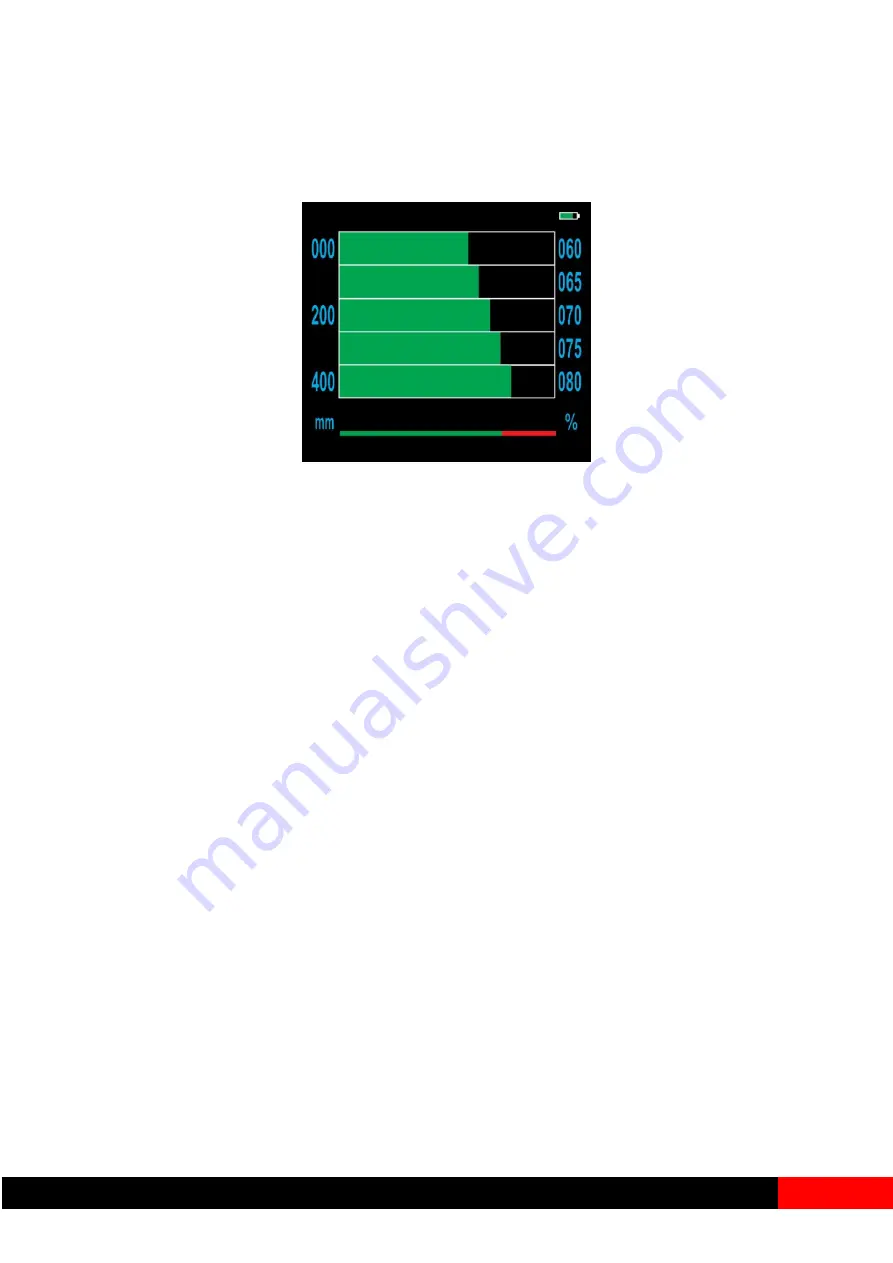
Inspecting Wall Loss: First scan
If, as you push the probe down the inside of the column, the tip of the probe passes a region
where there is wall loss, the bar graph readings will rise above zero, indicating the presence
of significant wall loss.
3.3
Continuing the Inspection
The probe ‘sees’ about one third of the circumference. It will not detect a defect on the far side
of the column unless the defect is very large.
To ensure that nothing is missed, insert the probe in four positions, roughly equally spaced
round the inside of the column. There is no need to reset the calibration at each insertion,
once set, it is good for the whole column.
If a re-zero is required, press the Down arrow, re-position the probe to the top part of the drive
coil and press the Down arrow again.
3.4
Finalising the Inspection
If there is a defect, the four scans will have shown its presence.
If a defect has been found, it is advisable to extend the inspection.
By moving the probe up and down, locate the mid-point of the corrosion area and mark the
probe level with the bottom of the door opening. Pull the probe back up until the display reads
zero (level with the bottom part of the drive coil and mark the probe. The distance between
the two marks is the depth of the defect. Push the probe back down to the defect point and
read the appropriate scale on the display. This will be the loss of wall thickness.
Make one or two scans at intermediate positions round the circumference to find the worst
area and gain information on the vertical and circumferential extent of the defect.


