


V04.00 | 2021/05
61
8.4.4
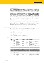
MRP (Media Redundancy Protocol)
The device supports MRP.
MRP is a standardized protocol according to IEC 62439. It describes a mechanism for media re-
dundancy in ring topologies. With MRP, a defective ring topology with up to 50 nodes is detec-
ted and reconfigured in the event of an error. With MRP a trouble-free switch-over is not pos-
sible.
A Media Redundancy Manager (MRM) checks the ring topology of a PROFINET network defined
by the network configuration for functionality. All other network nodes are Media Redundancy
Clients (MRC). In the error-free state, the MRM blocks normal network traffic on one of its ring
ports, with the exception of the test telegrams. The physical ring structure thus becomes a line
structure again at the logical level for normal network traffic. If a test telegram fails to appear, a
network error has occurred. In this case, the MRM opens its blocked port and establishes a new
functioning connection between all remaining devices in the form of a linear network topo-
logy.
The time between ring interruption and recovery of a redundant path is called reconfiguration
time. For MRP, this is a maximum of 200 ms. Therefore, an application must be able to com-
pensate for the 200 ms interruption. The reconfiguration time always depends on the Media
Redundancy Manager (e.g. the PROFINET PLC) and the I/O cycle and watchdog times set here.
For PROFINET, the response monitoring time must be selected accordingly > 200 ms.
It is not possible to use Fast Start-Up in an MRP network.
8.4.5
User data for acyclic services
The acyclic data exchange is by using via Record Data CRs (Communication Relation). Via these
Record Data CRs the reading and writing of the following services is realized:
n
Writing of AR data
n
Writing of configuration data
n
Reading and writing of device data
n
Reading of diagnostic data
n
Reading of I/O data
n
Reading of Identification Data Objects (I&M functions)
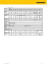
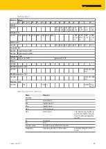
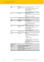
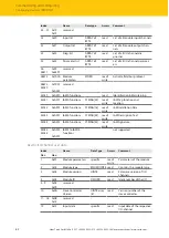
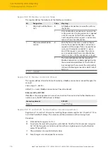
Acyclic device user data
Index
Name
Data type
Access
Comment
Dec.
Hex.
1
0x01
Module
parameters
WORD
read/
write
Parameter data of the module
(slot 0)
2
0x02
Module
designation
STRING
read
Designation assigned to the
module (slot 0)
3
0x03
Module revision
STRING
read
Firmware revision of the module
4
0x04
Vendor ID
WORD
read
Ident no. Turck
5
0x05
Module name
STRING
read
The device name assigned to
the module
6
0x06
Module type
STRING
read
Device type of the module
7
0x07
Device ID
WORD
read
Ident no. of the module
8…23
0x08…
0x17
reserved
-
-
-
24
0x18
Module
diagnostics
WORD
read
Diagnostic data of the module
(slot 0).
Содержание TBEN-S Series
Страница 1: ...Your Global Automation Partner Instructions for Use TBEN S Digital and Analog Modules ...
Страница 2: ...2 Hans Turck GmbH Co KG T 49 208 4952 0 F 49 208 4952 264 more turck com www turck com ...
Страница 29: ...V04 00 2021 05 29 Analog modules V1 V2 V1 V2 Fig 36 Power supply TBEN S2 4AI Fig 37 Power supply TBEN S2 4AO ...
Страница 244: ...Over 30 subsidiaries and over 60 representations worldwide www turck com 100001931 2021 05 100001931 ...


