background image


21


RUFNEK OIL BRAKE ASSEMBLY


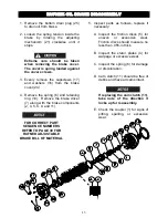
1.  Press the oil seal (27) into the brake 

housing (14).  Attach the brake 
housing to the gearbox with eight 
capscrews (15) using gasket (13).


2.  Install the key (12) and coupler (1) 

onto the worm.  Next, install the 
clutch/driver assembly (Items 2, 3, 7, 
8, 9, and 10), onto the coupler (1).


3. With the retaining ring (2) on the 

clutch driver (7).  Install the stator 
plates (4) and friction discs (5), in the 
correct layout as shown below.


4.  Install the spring (6).  


5. 

Install the adjusting mechanism 
assembly (assembled items 21, 22, 
and 23) into the brake cover (24) and 

attach the brake cover to the housing 
(14) with eight evenly installed 
capscrews (17) and washers (16).


6. Install the drain plug (25) into the 

bottom of the brake cover (24).


7.  Fill gearbox and brake with proper 

oil.  Refer to winch maintenance 
section of this manual for oil type and 
amounts.


8. Adjust the brake using the procedure 

on page 9 of this manual.


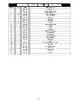
FOR CORRECT PART 

SEQUENCE NUMBERS 

REFER TO PAGE 30 FOR 

RUFNEK ADJUSTABLE 

BRAKE BILL OF MATERIAL 

Содержание RUFNEK 45

Страница 1: ...CLUTCH AND DRUM DISASSEMBLY 14 GEARBOX DISASSEMBLY 15 GEAR INSPECTION INSTRUCTIONS 16 ASSEMBLY 17 GEARBOX ASSEMBLY 17 DRUM BRAKE ASSEMBLY 18 ADJUSTABLE OIL BRAKE ASSEMBLY 19 NON ADJUSTABLE OIL BRAKE A...

Страница 2: ...ed by a qualified person All welding should also be done by a qualified person Winch mount must be flat so as not to induce binding The flatness must not exceed 1 16 inch across the mounting surface o...

Страница 3: ...ch is fully engaged before hoisting A visual inspection of the drum clutch engagement is required before each winching operation Must rig all loads secure before winching Pull the load line taut and i...

Страница 4: ...H BREAK IN Winches like any other kind of machinery require a break in to perform well and to maximize their life The following guidelines should be used in the break in of Tulsa Winches Use extreme c...

Страница 5: ...ion L Left R Right viewed from rear of truck Gear Type W Worm P Planetary Drive Type H Hydraulic M Mechanical Gearbox Position L Left R Right viewed from rear of truck Input Shaft Location F Front R R...

Страница 6: ...il level in the gearbox be checked and adjusted as part of the pre use inspection If the oil level drops frequently or oil leakage is detected during an inspection maintenance should be performed to c...

Страница 7: ...7 OIL LEVELS BRAKE OIL DRAIN BRAKE OIL LEVEL BRAKE FILL VENT GEARBOX OIL LEVEL GEARBOX FILL VENT GEARBOX OIL DRAIN...

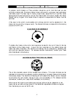
Страница 8: ...of holes in the top and bottom of the brake cover Loosen the two capscrews in the slotted holes and rotate the brake clockwise The direction of braking can be changed by replacing the cam with the opp...

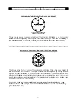
Страница 9: ...ULTIPLE DISC OIL BRAKE This brake is the Rufnek version of the adjustable oil brake This is the latest design of the worm driven winch brakes This style of brake can be adjusted by turning the hex adj...

Страница 10: ...ller to remove the brake drum 7 Inspect parts as follows replace if necessary A Inspect the brake shoes 86 for wear If the shoe linings are worn flush with the rivet heads the shoes must be replaced B...

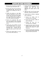
Страница 11: ...kwise to allow the spring to apply force to the cover 4 Remove the adjusting mechanism 14 from the brake cover 19 and inspect the o ring 26 replace it if necessary 5 Remove the spring 5 Grasp the brak...

Страница 12: ...13 to dislodge the cover 3 Remove the spring 11 then grasp the brake driver 6 and remove the brake components 4 Inspect the stator plates 9 friction discs 10 and retaining ring 8 for wear and replace...

Страница 13: ...ver 7 along with the brake components 2 4 5 8 9 and 11 5 Inspect parts as follows replace if necessary A Inspect the friction discs 5 for uneven or excessive wear Friction discs should measure no less...

Страница 14: ...41 or the clutch indicator assembly 90 Loosen the set screw 9 and remove the first collar 10 6 Remove the sliding clutch 11 keys 67 and the other collar 10 7 Remove the brake band assembly by removin...

Страница 15: ...ove the spacer 73 carrier 72 and keys 70 5 Remove the worm 57 from the housing by removing either the motor 90 and motor adapter 95 or the end cap 51 depending on type of drive From the brake end push...

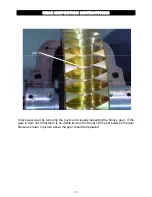
Страница 16: ...gear wear by removing the cover and visually inspecting the bronze gear If the gear is worn such that there is no visible land on the throat of the gear between the gear flanks as shown in picture ab...

Страница 17: ...p 51 Attach the end cap 51 to the housing 61 with six capscrews 56 using gasket 52 Install the key 58 onto the end of the worm 57 3 Install the keys 70 into the output shaft 68 4 Slide the carrier 72...

Страница 18: ...the worm shaft 57 Secure the brake drum with the nut 85 using washer 84 Bend two tabs of the washer 84 over the flats of the nut 85 3 If removed reattach the cam 88 to the brake cover 87 using two ca...

Страница 19: ...ates 3 and friction discs 4 in the correct stack up as shown below 4 Install the spring 5 Insert the adjusting mechanism assembly items 9 14 26 into brake cover 19 5 Attach the brake cover 19 with eig...

Страница 20: ...he brake housing 1 then install the stator plates 3 and friction discs 4 in the correct stack up as shown below 4 Install the spring 5 then press the washer 12 into the brake cover 13 5 Secure the bra...

Страница 21: ...he correct layout as shown below 4 Install the spring 6 5 Install the adjusting mechanism assembly assembled items 21 22 and 23 into the brake cover 24 and attach the brake cover to the housing 14 wit...

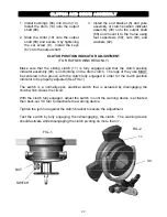
Страница 22: ...t the clutch position indicator assembly 90 is not binding on the drum clutch The lugs of the yoke MUST be centered in the groove with the clutch fully engaged in order for the clutch position indicat...

Страница 23: ...ed Winch runs too slow a Low flow rate Check the flow rate and increase if necessary b Hydraulic motor worn out Replace the motor Cable drum won t free spool a Winch not mounted squarely Check mountin...

Страница 24: ...7 45 106 80 64 1 2 20 85 64 51 120 90 72 9 16 12 109 82 65 153 115 92 9 16 18 122 91 73 172 129 103 5 8 11 150 113 90 212 159 127 5 8 18 170 128 102 240 180 144 3 4 10 266 200 160 376 282 226 3 4 16 2...

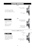
Страница 25: ...25 CLUTCH INSPECTION...

Страница 26: ...RUM 15 1 21163 U BOLT 16 3 20325 CAPSCREW 17 4 21775 DRIVE SCREW 18 OMIT 19 8 20520 WASHER 20 4 20274 NUT 21 5 20521 NUT 22 1 20958 SPRING 23 12 20526 WASHER 24 11 20271 NUT 25 1 20179 ROD 26 19 20267...

Страница 27: ...RAKE OR NON ADJ 57i 1 20767 MECHANICAL R H WORM W SHOE BRAKE OR NON ADJ 57j 1 40764 16 TOOTH INPUT L H WORM W SHOE BRAKE OR NON ADJ 57k 1 40665 17 TOOTH INPUT L H WORM W SHOE BRAKE OR NON ADJ 58 1 203...

Страница 28: ...88a 1 20685 RIGHT HAND CAM 88b 1 20687 LEFT HAND CAM 89 1 20677 HOUSING 90 1 4363 CLUTCH POSITION INDICATOR KIT 91a 1 40425 MOTOR 16 TOOTH INPUT 91b 1 40666 MOTOR 17 TOOTH INPUT 92 4 20310 CAPSCREW 9...

Страница 29: ...19 1 41409 BRAKE COVER 20 1 32220 PIPE PLUG 21 1 12208 BUSHING 22 1 20315 GASKET 24 1 20278 CAPSCREW 25 1 41419 WASHER 26 1 41411 O RING 27 1 13050 BREATHER NON ADJUSTABLE BRAKE BILL OF MATERIAL SEQ...

Страница 30: ...DRIVER 8 2 41743 BUSHING 9 2 41723 RACE 10 1 26980 RETAINING RING 11 1 41759 CLUTCH 12 1 25519 KEY 13 1 20315 GASKET 14 1 33177 BRAKE HOUSING 15 8 33212 CAPSCREW 16 8 20289 CAPSCREW 17 8 20526 LOCKWAS...

Страница 31: ...31 ISOMETRIC VIEW FOR ADJUSTABLE OIL BRAKE AND HYDRAULIC MOTOR SEE PAGE 32...

Страница 32: ...HYDRAULIC MOTOR ADJUSTABLE OIL BRAKE CLUTCH POSITION INDICATOR MOTOR VIEW ADJUSTABLE OIL BRAKE CLUTCH POSITION INDICATOR KIT TWG PO Box 1130 Jenks OK 74037 1130 USA Phone 918 298 8300 www dovertwg co...

Отзывы: