


-15-
Regular maintenance and inspection are indispensable to maintaining the pump's performance. If the
pump behaves differently from its normal operating condition, refer to section "9. Troubleshooting" and
take appropriate measures at an early stage. We also recommend that you have a spare pump on hand
for an emergency.
Prior to Inspection
Make sure that the power supply (i.e. circuit breaker) is disconnected and
disconnect the cabtyre cable from the power outlet or remove it from the
terminal board. Failure to do so may cause electrical shock or unintended
starting of the pump, which may lead to serious accidents.
(1) Washing the Pump
Remove any debris attached to the pump's outer surface, and wash the pump with tap water. Pay
particular attention to the impeller area, and completely remove any debris from the impeller.
(2) Inspecting the Pump Exterior
Verify that there is no damage, and that the bolts and nuts have not loosened.
If the pump must be disassembled for repair due to damage or loose bolts or nuts, contact the dealer where
it was purchased, or the Tsurumi sales off ce in your area.
WARNING
Note:
Daily and Periodic Inspection
Refer to section "Oil Inspection and Change Procedures" below for further detail.
Note:
In case the pumping liquid contains oil, paint, or slurry, it may cause the swelling of cable jacket or abrasion
of the mechanical seal's sealing face, which will result in the pump fault, it is strongly recommended to
inspect earlier.
Note:
7 MAINTENANCE AND INSPECTION
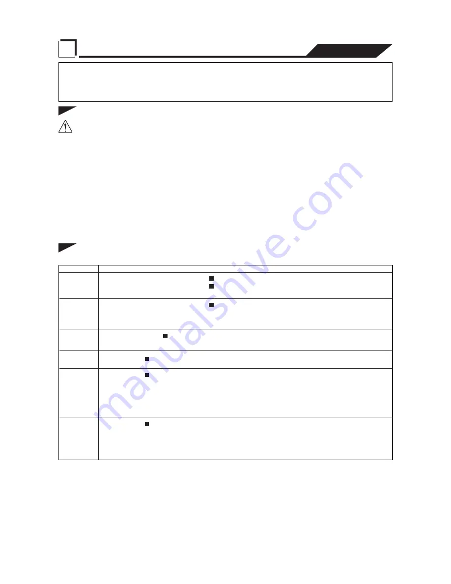
Interval
Monthly
Daily
Half-yearly
Inspection Item
Yearly
Once every
2 years
Once every
2 to 5 years
Measuring the operating current
Measuring the insulation resistance
[NOTE] The motor must be inspected if the insulation resistance is considerably lower
than the last inspection.
Inspecting oil
[NOTE] The inspection and replacement of the mechanical seal requires specialized
equipment. To have this operation performed, contact the dealer where this
equipment was purchased, or the Tsurumi sales office in your area.
Overhaul
[NOTE] To overhaul the pump, contact the dealer where it was purchased, or the
Tsurumi sales office in your area.
9,000 hours or 24 months, whichever comes first
Changing the mechanical seal
Power supply voltage tolerance
= within ± 5% of the rated voltage
Measuring the power voltage
To be within the rated current
Insulation resistance reference value = 1MΩ minimum
The pump must be overhauled even if the pump appears normal during operation.
Especially, the pump may need to be overhauled earlier if it is used continuously.
Inspection of liffting
chain or rope
Replace if damage, corrosion, or wear has occurred to the chain or rope.
Remove if foreign object is attaching to it.
Changing oil
6,000 hours or 12 months, whichever comes first


