3
Installation and Usage
1. Recommended shaft tolerance is shown below. Interference fit and shrink fit are prohibited for clutch fixing.
Clutch Bore
Shaft Fit Guide
1.20 to 2.00 inches dia.
30mm to 50mm dia.
Line fit to .0010 inches loose
(0.025mm)
2.00 to 3.15 inches dia.
50mm to 80mm dia.
Line fit to .0012 inches loose
(0.030mm)
3.15 to 4.70 inches dia.
80mm to 120mm dia.
Line fit to .0014 inches loose
(0.036mm)
4.70 to 7.10 inches dia.
120mm to 180mm dia.
Line fit to .0016 inches loose
(0.041mm)
7.10 to 9.85 inches dia.
180mm to 250mm dia.
Line fit to .0018 inches loose
(0.046mm)
9.85 to 12.40 inches dia.
250mm to 315mm dia.
Line fit to .0020 inches loose
(0.051mm)
12.40 to 15.70 inches dia.
315mm to 400mm dia.
Line fit to .0023 inches loose
(0.058mm)
15.70 to 17.72 inches dia.
400mm to 500mm dia.
Line fit to .0025 inches loose
(0.064mm)
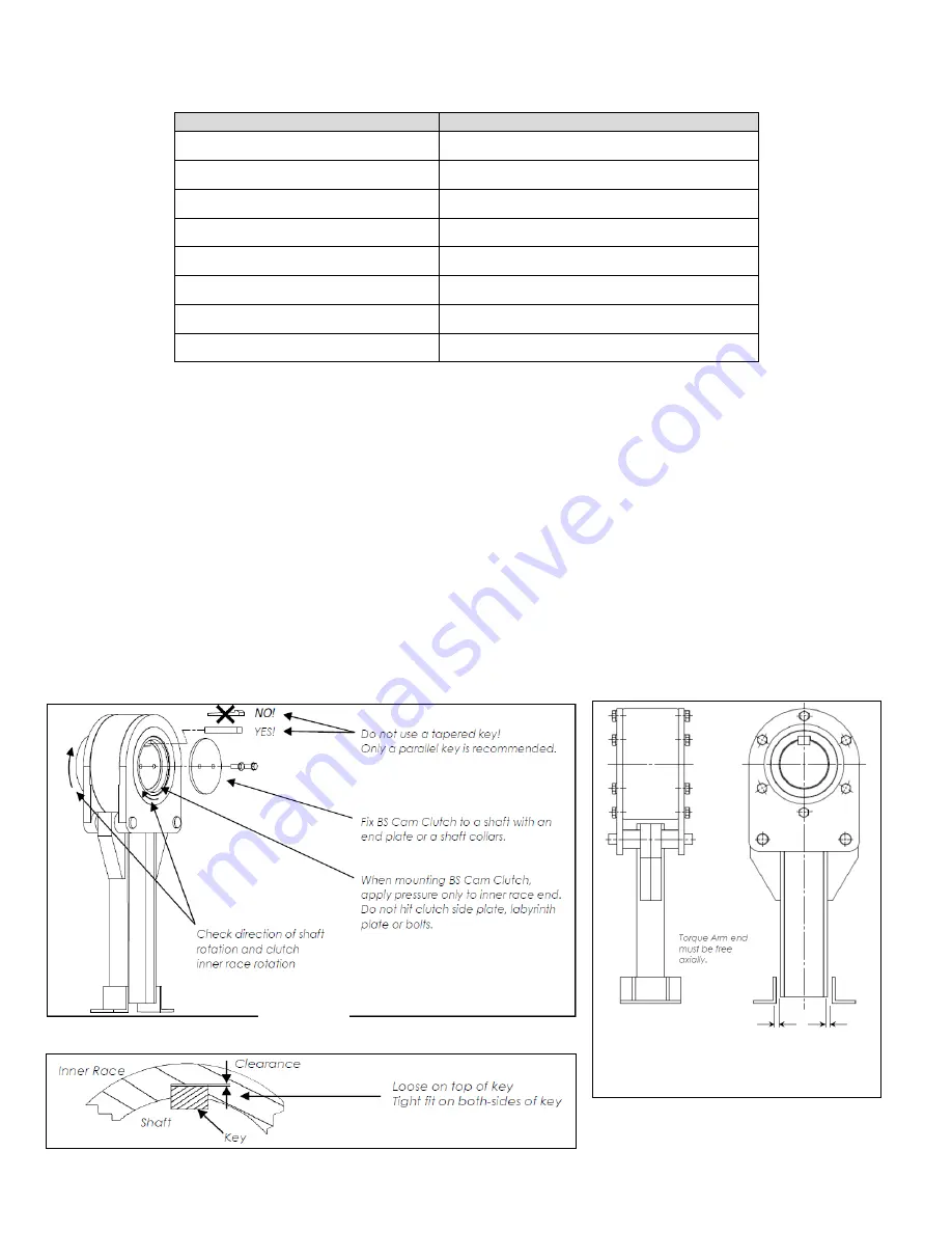
2. Before installation, verify that the rotation of inner race is in the same direction as the direction of the conveyor shaft.
3. Clean the shaft and remove burrs.
4. Only a parallel key is recommended for Backstop fixing. Do not use a tapered key. And there must be clearance between
Backstop keyway and key top. The key should be in accordance with ANSI B17, 1-1967 (R 1998). See Fig 1 and 2.
5. Apply pressure only on the end face of inner race when installing the Backstop onto the shaft. Do not hit the side plate, labyrinth
plate or bolts with a hammer. See Fig 1.
6. Lift torque arm and attach it to the Backstop with torque arm pins and cotter pins with Backstop. Coat pins with grease for easy
mounting of the Backstop and preventing stuck pins.
7. The end of torque arm will move to some extent while the conveyor is operating. Support the torque arm end only in the direction
of rotation, be sure to allow it a certain amount of free movement axially. See Fig 3. The Backstop sustains damage if the torque
arm end tip is fixed securely.
8. In order to suppress the temperature rise of Backstop and to extend the lubricant life, installation of a protective cover against
direct sunshine is recommended.
Fig 3
Total clearance should
be between 0.1 to 0.2
i
h
Fig 1
Fig 2
Содержание BS115F
Страница 8: ...b...


