5
PEX-1000 Series
Print Engine Service Manua
l
2. ELECTRONICS
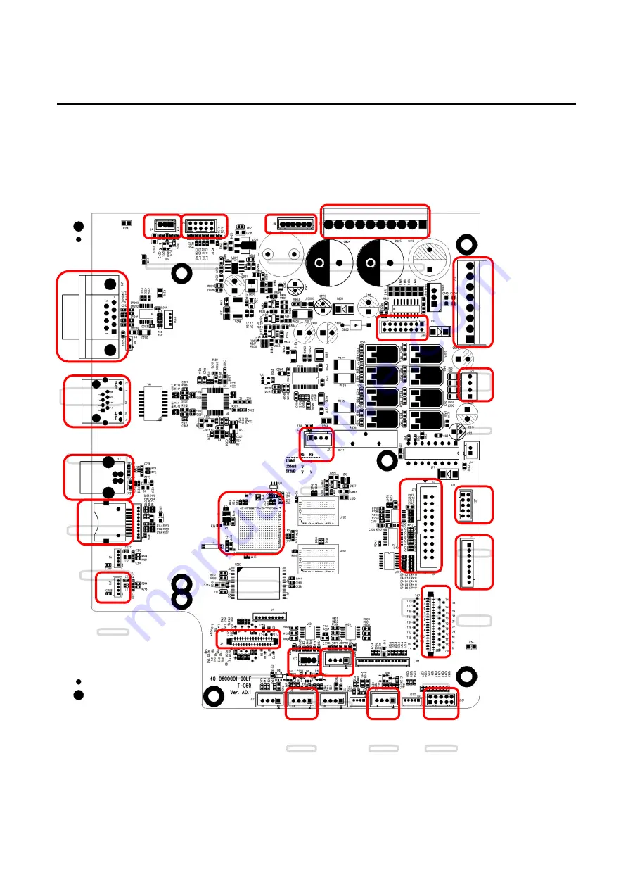
2.1 Summary of Board Connectors
1
21
3
9
2
16
17
18
19
13
140
100
7
8
15
11
22
24
23
20
6
4
12
Страница 1: ...SERVICE MANUAL THERMAL TRANSFER DIRECT THERMAL PRINT ENGINE PEX 1120 PEX 1130 PEX 1160 Series PEX 1220 PEX 1230 PEX 1260 Series ...
Страница 2: ...ics Cover 13 3 4 Replacing the Power Supply Unit 14 3 5 Replacing Multi interface GPIO parallel Board 16 3 6 Replacing the Main Board 19 3 7 Replacing the Gap Black Mark Sensor Module 20 3 8 Replacing the Panel Control Board LCD Panel 22 3 9 Replacing the Bluetooth Module Wi Fi Module 24 3 10 Replacing the Stepping Motor Assembly 25 3 11 Replacing the Peel off Roller Module 26 4 TROUBLESHOOTING 31...
Страница 3: ... configuration PEX 1120 PEX 1130 PEX 1160 series PEX 1220 PEX 1230 PEX 1260 series Left hand model Right hand model Note This document is going to show the components inside the media compartment of a left hand print engine A right hand unit contains a mirror image of those components Familiarize yourself with those components before continuing with the print engine setup procedure ...
Страница 4: ...rint Engine Service Manual 1 2 Overview Front View 1 Soft keys 2 Power switch 3 LCD display 4 Wi Fi antenna option 5 LED indicator 6 Navigational keys 7 Media view window 8 Print engine cover 9 USB host 2 1 3 4 6 7 5 8 9 ...
Страница 5: ... adjustment knobs 3 Print head pressure adjustment knobs 4 Print head release lever 5 Print engine cover open sensor 6 Ribbon supply spindle 7 Label guide bar release lever 8 Media sensor position adjustment knob 9 Platen roller 10 Print head 11 Media sensor 12 Label guide 2 1 3 4 6 5 8 9 10 2 11 12 7 ...
Страница 6: ...Class 10 UHS I 16G Scandisk The DOS FAT file system is supported for the SD card Folders files stored in the SD card should be in the 8 3 filename format The miniSD microSD card to SD card slot adapter is required 1 GPIO interface Applicator interface with DB15F connector 5V I O 2 RS 232C interface 3 Ethernet interface 4 USB interface 5 Power cord socket 6 Centronics interface 7 Micro SD card sock...
Страница 7: ...5 5 PEX 1000 Series Print Engine Service Manual 2 ELECTRONICS 2 1 Summary of Board Connectors 1 21 3 5 9 2 16 17 18 19 13 14 0 10 0 7 8 15 11 22 24 23 20 1 6 4 12 ...
Страница 8: ...ap sensor connector 8 Ribbon encoder sensor connector 9 Power supply output 24V DC connector 10 BM Sensor connector 11 Paper Distance Sensor connector 12 BT module connector 13 Print head connector 14 LCD panel connector 15 Ribbon end sensor connector 16 TPH Power 24V DC connector 17 Stepping motor connector 18 Cutter peel off connector 19 Paper REWIND connector 20 Micro processor 21 RS 232C conne...
Страница 9: ...rvice Manual 2 2 Interface Pin Configuration RS 232C PIN CONFIGURATION 1 5 V 2 TXD 3 RXD 4 CTS 5 GND 6 RTS 7 N C 8 RTS 9 N C USB PIN CONFIGURATION 1 N C 2 D 3 D 4 GND Ethernet PIN CONFIGURATION 1 Tx 2 Tx 3 Rx 4 N C 5 N C 6 Rx 7 N C 8 N C ...
Страница 10: ...int Engine Service Manual GPIO Applicator interface with DB15F connector 5V I O Pin CONFIGURATION 1 GND 2 5V JP2 short 3 GPI_1 4 GPI_2 5 GPI_3 6 GPI_4 7 24V 8 GND 9 GPO_1 10 GPO_2 11 GPO_3 12 GPO_4 13 GPO_5 14 GPO_6 15 GPO_7 ...
Страница 11: ...ngine cover 2 Disengage print head release lever 3 Remove three screws on the platen holder Left hand model Right hand model 4 Take out the platen holder tear bar and platen roller assembly and replace a new platen roller assembly 5 Reassemble the parts in the reverse procedures Platen roller assembly Platen holder ...
Страница 12: ...lease lever Left handed configuration Right handed configuration 3 Carefully disconnect connectors from the print head assembly Please do not pull the cable to right and left side alternatively in order to disconnect it from the print head connector Please use the flat screw driver to push at the key in the middle of the connector When the connector becomes loose from the print head connector you ...
Страница 13: ...int head cable and carefully slide print head assembly into the print mechanism Make sure the two locating protrusion pins on the print mechanism mounting plate snap into the locating holes on the print head Locating protrusions Locating holes Locating protrusions Locating holes Locating holes Locating holes ...
Страница 14: ...en totally closed to the print mechanism before secure the print head by the previously removed thumbscrew 7 Reassemble the parts in the reverse procedures Note Please use the come with new print head secure screw to replace the print head assembly DO NOT re use the original screw ...
Страница 15: ...s Print Engine Service Manual 3 3 Remove the Electronics Cover 1 Remove four screws on the electronics cover 2 Draw out the electronics cover to remove it 3 Reassemble the parts in the reverse procedures Electronics cover ...
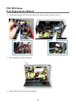
Страница 16: ...1000 Series Print Engine Service Manual 3 4 Replacing the Power Supply Unit 1 Refer to section 3 3 to remove the electronics cover 2 Disconnect three connectors as shown 3 Remove two screws on power supply cover ...
Страница 17: ...0 Series Print Engine Service Manual 4 Pull the power supply unit to loosen the cable tie and disconnect one connector as shown 5 Remove Replace the power supply unit 6 Reassemble the parts in the reverse procedures ...
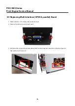
Страница 18: ...ng Multi interface GPIO parallel Board 1 Refer to section 3 3 to remove the electronics cover 2 Remove two screws on main board cover 3 Disconnect the connectors as below shown first then disconnect all connectors on the main board to take out the main board unit ...
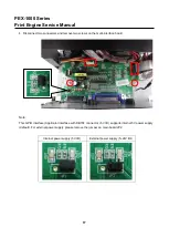
Страница 19: ...ve two screws on the multi interface board Note This GPIO interface Applicator interface with DB15F connector 5V I O supports internal 5V power supply default For external power supply please remove the jumper on main board JP2 Internal power supply 5V I O External power supply 5 24V I O ...
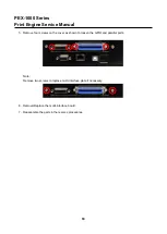
Страница 20: ...nual 5 Remove four screws on the cover as shown to loosen the GPIO and parallel ports Note Remove two screws to replace multi interface plate if necessary 6 Remove Replace the multi interface board 7 Reassemble the parts in the reverse procedures ...
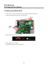
Страница 21: ...to section 3 3 3 5 to remove the electronics cover and multi interface board first 2 Remove two copper pillars four screws on the main board 3 Remove two screws to loosen the serial port 4 Remove Replace the main board 5 Reassemble the parts in the reverse procedures Copper pillars Screws ...
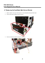
Страница 22: ...g the Gap Black Mark Sensor Module 1 Refer to section 3 6 to remove all connectors on the multi interface board and main board 2 Pull the lower drawer interface unit and remove it 3 Pull the media sensor module and loosen the cable ties Lower drawer interface unit ...
Страница 23: ...21 21 PEX 1000 Series Print Engine Service Manual 4 Remove Replace the gap black mark sensor 5 Reassemble the parts in the reverse procedures Gap black mark sensor connectors ...
Страница 24: ...8 Replacing the Panel Control Board LCD Panel 1 Refer to section 3 3 3 4 and 3 5 to remove the electronics cover power supply unit and interface unit 2 Remove the marked fix LCD panel module two screws 3 Loosen cable ties to remove the LCD panel assembly ...
Страница 25: ...ut and washer as shown to open the LCD cover 6 Remove two screws three cables and open the USB host cover to replace the panel control board LCD panel Note Please unlock the plug from connect for the flat cable and carefully pull the flat cable free 7 Reassemble the parts in the reverse procedures Hex nut Washer ...
Страница 26: ...he previous section 3 8 to open the LCD cover 2 For Bluetooth module disconnect one cable connector and four screws to replace it For Wi Fi module disconnect one cable connector three screws and one antenna connector to replace it 3 Reassemble the parts in the reverse procedures Bluetooth module Wi Fi module ...
Страница 27: ...ious step refer to section 3 3 3 4 and 3 5 to remove the electronics cover power supply unit and interface unit 2 Remove four screws and one connector on the stepping motor assembly 3 Remove Replace the stepping motor assembly including belt gears stepping motor 4 Reassemble the parts in the reverse procedures ...
Страница 28: ...e Peel off Roller Module 1 Open the peel off roller release lever Left handed configuration Right handed configuration 2 Turn the thumb screw on the peel off roller module to remove replace the peel off roller module Left handed configuration Right handed configuration ...
Страница 29: ...e is a locating hole between media sensor and rear paper feed roller most right one Left handed configuration Right handed configuration 4 Put the shaft of the peel off roller module into the locating hole Left handed configuration Right handed configuration ...
Страница 30: ...ce Manual 5 After putting shat into locating hole at certain angle the module would not be able to put inside Please turn the module in the clockwise direct to put the module inside Left handed configuration Right handed configuration 1 2 1 2 ...
Страница 31: ...anual 6 Put back the golden color screw and turn it in the clockwise direction to fix the screw Left handed configuration Right handed configuration 7 Pushing the peel off roller module upward Left handed configuration Right handed configuration ...
Страница 32: ...es Print Engine Service Manual 8 After hearing the click sound the module is fixed to its position without dangling Finished the installation of peel off roller module Left handed configuration Right handed configuration ...
Страница 33: ...ers No Ribbon Running out of ribbon The ribbon is installed incorrectly Supply a new ribbon roll Please refer to the steps in user s manual to reinstall the ribbon No Paper Running out of label The label is installed incorrectly Gap black mark sensor is not calibrated Gap black mark sensor is not on the media Supply a new label roll Please refer to the steps in user s manual to reinstall the label...
Страница 34: ...tting again Chang a new cable Ribbon and media are not compatible Verify the ribbon inked side Reload the ribbon again Clean the printhead The print density setting is incorrect Printhead s harness connector is not well connected with printheat Turn off the printer and plug the connector again Check if the stepping motor is plugging in the right connector Check your program if there is a command P...
Страница 35: ...ation is unsuccessful Turn OFF and ON the printer again Initialize the printer LCD panel is dark and LEDs are lit on but the label is feeding forward The LCD panel harness connector is loose The LCD panel harness connector is plugged upside down Ribbon encoder sensor doesn t work The ribbon encoder sensor connector is loose Fasten the connector Ribbon end sensor doesn t work The connector is loose...
Страница 36: ...correct Ribbon installation is incorrect Media installation is incorrect Print density is incorrect Media feeding is incorrect Please refer to the 5 2 chapter Please set the suitable density to have good print quality Make sure the label guide touch the edge of the media guide Gray line on the blank label The printhead is dirty The platen roller is dirty Clean the printhead Clean the platen roller...
Страница 37: ...characteristics print darkness setting etc In case the ribbon wrinkle happens please follow the instructions below to adjust the printer parts Pressure position The pressure position can be adjusted by using a coin Please use a coin to release the fixing screws as below show When using label its width is smaller than 2 inch Please release the right side of pressure knob Only use left side pressure...
Страница 38: ...ustment 1 Decrease the right side print head pressure adjustment knob setting 1 level per each adjustment then print the label again to check if wrinkle is gone 2 If the right side print head adjustment knob setting has been set to index 1 the lowest pressure index please increase the left side print head pressure If the wrinkle on the label starts from the lower right side to upper left side plea...
Страница 39: ... 3 Adjusting Heater Line 1 Release 2 lock screws before you start to adjusting heater line screws 2 Adjust heater line by right side and left side heater line adjusting screws Heater line lock Heater line lock Heater line adjust screw Heater line adjust ...
Страница 40: ...t be easy seeing the uneven printing if using too high density to print the black bar For 200dpi printer below is example command line for adjusting heater line SIZE 102 5 mm 63 5 mm GAP 0 08 0 SPEED 8 DENSITY 0 REFERENCE 0 48 DIRECTION 0 0 SET TEAR ON CLS BAR 8 18 99 8 30 8 TEXT 142 360 ROMAN TTF 0 8 8 SPEED GETSETTING CONFIG TSPL SPEED TEXT 142 390 ROMAN TTF 0 8 8 DENSITY GETSETTING CONFIG TSPL ...
Страница 41: ...ON SERIAL PRINT 1 5 The lighter black bar may like left picture 6 But sometime you can see one side has lighter density as below picture 7 For this situation please adjust right side heater line adjustment knob by clockwise direction until you see good density full average black ...
Страница 42: ...e may become a little white In this time you may need to adjust left side knob 8 Until both side is full average black like the first one picture Or like left side picture 9 If you keep turning the heater over the best position it may look like below picture again Right side is lighter again ...
Страница 43: ...e even picture I show you 11 Then after adjusting it lock the 2 locking screws to fix the heater line position Note For different thickness label you may need to print out such pattern to see if this heater line is fit with this heat line position or not If you find that even with the lowest speed and highest density the density is still not enough you can try to do this test to adjust heat line ...
Страница 44: ...hod Interval Print Head 1 Always turn off the printer before cleaning the print head 2 Allow the print head to cool for a minimum of one minute 3 Use a cotton swab Head cleaner pen and 100 ethanol to clean the print head surface Clean the print head when changing a new ribbon roll Platen Roller 1 Turn the power off 2 Rotate the platen roller and wipe it thoroughly with a cotton swab or lint free c...
Страница 45: ...th As needed Interior Brush or vacuum As needed Note Do not touch printer head by bare hand If you touch it careless please use ethanol to clean it Please use 100 Ethanol DO NOT use medical alcohol which may damage the printer head Regularly clean the print head and supply sensors once change a new ribbon to keep printer performance and extend print head life ...
Страница 46: ...00 Series Print Engine Service Manual 44 44 UPDATE HISTORY Date Content Editor 2019 1 4 Modify GPIO information update pictures Add GPIO interface Pin configuration Camille 2019 9 4 Modify section 2 1 Camille ...
Страница 47: ...ng 1st Rd Wujie Township New Taipei City 23141 Taiwan R O C Yilan County 26841 Taiwan R O C TEL 886 2 2218 6789 TEL 886 3 990 6677 FAX 886 2 2218 5678 FAX 886 3 990 5577 Web site www tscprinters com E mail apac_sales tscprinters com tech_support tscprinters com TSC Auto ID Technology Co Ltd ...