background image

1.

Safety

1.1

General safety information

Read all the safety information and instructions including
those in the brochure also supplied.

Failure to comply with the safety information and instructions
can cause electric shock, burns and/or serious injury.

Retain all the safety information and instructions for future
use.

Electrical voltage! Risk of fatal injury due to electric shock!

Ø

Remove the plug from the plug socket before undertaking
any maintenance work on the machine.

Ø

Check the plug, cable and machine for damage each time
before using the machine.

Ø

Keep the machine dry and do not operate it in damp rooms.

Ø

Connect the fault current (FI) circuit breaker with a maximum
breaking current of 30 mA when using the electric tool out-
side.

Ø

Protect the machine cable in areas where there are sparks.

Ø

Only use original TRUMPF accessories.

Damage to the machine due to improper handling.

Ø

Wear safety glasses, hearing protection, protective gloves
and working shoes when working.

Ø

Connect the plug only when the machine is switched off.
Pull the power plug after use.

Ø

Do not carry the machine by the cable.

Ø

Have maintenance carried out by specialists.

1.2

Specific safety information for nibbler

Electrical voltage! Risk of fatal injury due to electric shock!

Ø

Always lay the power cable away from the back of the
device and do not pull it over sharp edges.

Ø

Do not perform any work that may cause the machine to
come into contact with hidden power lines or its own cable.
Contact with a live conductor can cause metallic machine
parts to become live and can lead to an electric shock.


E232en_06

Safety

3

 DANGER

 WARNING

 DANGER

Содержание TruTool N 1000

Страница 1: ...Operator s manual TruTool N 1000 1B1...

Страница 2: ...tion 14 4 1 Working with TruTool N 1000 15 4 2 Changing the cutting direction 15 4 3 Nibbling with templates 16 4 4 Producing interior cutouts 16 5 Maintenance 17 5 1 Replacing the tool 17 Changing th...

Страница 3: ...using the electric tool out side Protect the machine cable in areas where there are sparks Only use original TRUMPF accessories Damage to the machine due to improper handling Wear safety glasses heari...

Страница 4: ...t and sharp chips Chips exit the chip ejector at high speed Use a chip bag Risk of injury from falling machinery The entire weight of the machine must be taken up after machining the workpiece Use the...

Страница 5: ...g 54784 2 1 Intended use The TRUMPF Nibbler TruTool N 1000 is an electrically operated hand held device for Cutting of plate shaped workpieces made of a punchable material such as steel aluminum nonfe...

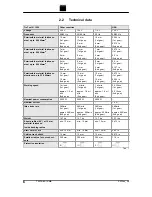
Страница 6: ...m 2nd gear 12 mm 1st gear 10 mm 2nd gear 12 mm 1st gear 10 mm 2nd gear 0 472 in 1st gear 0 394 in 2nd gear Working speed 1 m min 1st gear approx 1 6 m min 2nd gear 1 m min 1st gear approx 1 6 m min 2n...

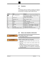
Страница 7: ...Power power input mm Millimeters Dimensions e g material thickness chamfer length in Inch Dimensions e g material thickness chamfer length no Idle speed Revolution speed without load min Revolutions...

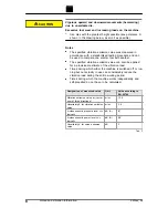
Страница 8: ...mate of the vibration load Times during which either the machine is switched off or run ning but not actually in use can considerably reduce the vibration load during the entire working period Times d...

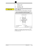
Страница 9: ...atest height possible keep distance X shown in the drawing below as small as possible 1 Die see following table 5 Punch guide 9 Punch W Workpiece X Distance between sheet surface and punch guide Fig 1...

Страница 10: ...minum 250 N mm2 5 5 7 7 10 10 12 Mild steel 400 N mm2 5 5 7 7 10 Stainless steel 600 N mm2 5 5 7 Stainless steel 800 N mm2 5 Material thickness in mm when machining profiles e g workpieces with press...

Страница 11: ...material thickness tensile strength and type of workpiece a different gear must be selected for machining Instead of in 2nd gear 1st gear can always be worked with but never vice versa Damage to prop...

Страница 12: ...54784 1 Put the machine into a stable position 2 Switch on the machine briefly Press the release switch 3 Press the On switch 1 and Off switch 2 at the same time 3 While the motor is running down turn...

Страница 13: ...9 has reached its maximum penetration depth 2 Open the locking mechanism Note One rotation of 360 corresponds to a height adjustment of 1 75 mm 3 Rotate the die carrier 7 by 360 as often as needed un...

Страница 14: ...the machine When using an extension cord that is longer than 5 m the cord must have a line diameter of at least 2 5 mm Damage to property due to turning the gear switch during operation Damage to the...

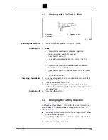
Страница 15: ...d move the machine toward the workpiece 4 Process the desired cutting line 5 If the cutting track ends in the sheet retract the running machine a few millimeters in the direction of the already free c...

Страница 16: ...The template must be at least 5 mm thick There must be a clearance of 15 5 mm between the contour of the template and the contour to be nibbled out The nibbler must be guided in such a way that the ex...

Страница 17: ...otects the machine Change the cutting tool in a timely manner Maintenance point Procedure and interval Recommended lubricant Lubricant order number Punch die and wear parts Check every hour Punch Regr...

Страница 18: ...late 7 Die holder 9 Punch 14 Clamping screw F Tube of lubricating grease S1 Fig 9764 Changing the punch 1 Loosen the clamping screw 14 2 Rotate the die holder 7 by 45 3 Pull the die holder 7 downward...

Страница 19: ...carrier 7 3 Clean the replacement parts if necessary Note To grease use lubricating grease S1 order num ber 121486 4 Lubricate the guide surfaces of the punch guide Note Use original screws only 5 Ti...

Страница 20: ...reserve for punch 5 85 mm 12 mm Tab 8 X Minimum length Fig 9017 1 Regrind the grinding surface according to the sketch paying attention to good cooling 2 Dress the cutting edge lightly with a fine oi...

Страница 21: ...ve wear Note Excessive wearing can overload the machine and lead to a wor sening of the cutting quality 1 Raised part 2 Depression Fig 9762 The wearing plate must be replaced when The raised part 1 is...

Страница 22: ...dealer to avoid safety haz ards Note For TRUMPF service addresses see www trumpf power tools com 5 5 Replacing carbon brushes The motor comes to a standstill whenever the carbon brushes are worn out N...

Страница 23: ...ope of deliv ery Handle 0103555 X Allen key DIN 911 12 0067920 X Allen key 0118860 X 2 cap screws M14x45 for fastening the handle DIN 912 0105083 X Adjusting gauge 1411767 X Operator s manual 0120218...

Страница 24: ...ery type e g air mail courier express mail ordinary freight parcel post Note For TRUMPF service addresses see www trumpf powertools com 4 Send the order to the TRUMPF representative office 24 Accessor...

Страница 25: ...7 Appendix Declaration of conformity guarantee replacement parts lists E232en_06 Appendix Declaration of conformity guarantee replacement parts lists 25...

Страница 26: ...26 Appendix Declaration of conformity guarantee replacement parts lists E232en_06...

Отзывы: