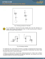
Notwithstanding it may be advantageous for dosing applications to install the Flowmeter as close
as possible to the dosing valve, since soft pipes increases the cross-section depending on the
system pressure. This may lead to repeatable differences.
When using pumps, Flowmeter must be installed in flow direction on the pressure side, on order to
ensure sufficient pressure. The maximum pressure rating of Flowmeter has to be considered.
For correct volume flow measurements straight and unobstructed inflow and outflow distances have
to be observed. Starting from the connection thread these straight and unobstructed flow zones
must be:
Particles present in the flow stream may result in measuring errors.
Insure that no cavitations dissolve from the measured liquid. Depending on the measured
liquid it can be helpful to have enough back pressure on the outlet of Flowmeter to avoid
cavitations. Insure all mechanical connections are tight.
NOTICE
NOTICE
Do not exceed the maximum pressure allowance for of the Flowmeter (see section
5.2 Technical specifications). Exceed the maximum pressure can lead to destruction
of the Flowmeter.
WARNING!
2.2 Assembly of the flow meter
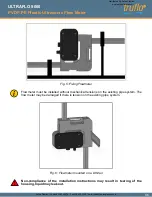
The flow meter is mounted into a pipe system by using the mechanical connection.
Flowmeter should be mounted vertically into the pipe for the best measuring performance. Do
not install the flow meter after a dosing valve where the flow meter can run empty. Placing
the flow meter after a dosing valve and allowing it to run empty will cause a measuring
deviation at the next measurement. To avoid bubbles in the liquid, Flowmeter should be
installed on the pressure side of the pump.
Nominal Diameter
Inflow distance
Outflow distance
DN 5
0cm
0cm
DN 7
0cm
0cm
DN 10
5cm
0cm
DN 15
40cm
20cm
04
PVDF-PE Plastic Ultrasonic Flow Meter
ULTRAFLO 5000
Distributed By Aetna Plastics
www.aetnaplastics.com
Aetna Plastics - Phone 800.634.3074 - Fax 216.524.2280 - Email [email protected]


