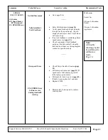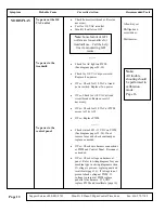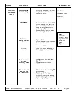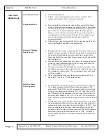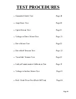
TEST PROCEDURES
Support Services 800-883-8783
Mon-Fri 8:30am-5:00pm Central Time Zone
Fax: 636-272-7148
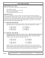
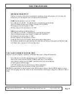
SPEED SENSOR TEST
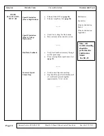
This test is used to verify sensor operation in conditions of speed fluctuation, E2: Cal error, S4:
Sensor error, E2: Overspeed error or Unsuccessful Calibration.
SS100
(Serial numbers 5-xxxx to 6-7999)
Set voltmeter to Volts DC. Treadmill power on speed and speed at 0mph
Attach voltmeter leads across outside 2 contacts at P2 on PWM
With magnet in front of sensor, 0 VDC
With no magnet in front of sensor, 3.0 VDC
SS90
(Serial numbers 6-8000 and above)
Set voltmeter to volts DC. Treadmill power on and speed at 0 mph
Attach voltmeter leads across outside 2 contacts at J1 on PWM
With magnet in front of sensor, 0 VDC
With no magnet in front of sensor, 5 VDC
Check the sensor on every magnet, adjust sensor until voltage shows
In calibration mode before pressing Start, the tread belt can be moved manually and the Met light
will blink when a magnet is in front of the sensor.
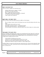
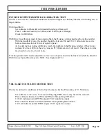
VOLTAGE TO DRIVE MOTOR TEST
This test is used to diagnose conditions of NO Belt Movement, or Speed Fluctuations
Set voltmeter to volts DC and adjust speed on Control Panel to 4 mph
Attach red voltmeter lead to MTR1 on PWM with motor wires attached
Attach black voltmeter lead to MTR2 on PWM with motor wires attached
0 VDC signals no PWM output
166 VDC signals open circuit in motor or motor connection
Operating voltage will lay between 0 VDC and 166 VDC
NOTE:
The reason that we do not narrow down PWM output voltage is that the PWM output is a pulse
signal. The sampling rate of the voltmeter used will determine what output voltage the voltmeter is able to
read.
Page 21
Содержание 350 Black
Страница 20: ...Page 18...
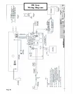
Страница 28: ...Page 26 350 Gray Wiring Diagram...
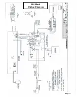
Страница 29: ...Page 27 350 Black Wiring Diagram...
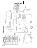
Страница 30: ...Page 28 400 Wiring Diagram...
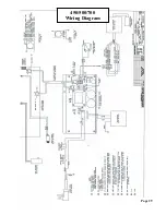
Страница 31: ...Page 29 450 500 700 Wiring Diagram...
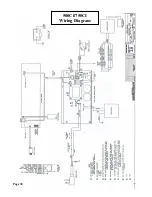
Страница 32: ...Page 30 500CI 750CI Wiring Diagram...
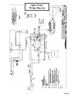
Страница 33: ...Page 31 500CI 750CI Wiring Diagram...
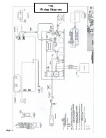
Страница 34: ...Page 32 750 Wiring Diagram...

