background image


27

TWO-WHEEL CENTERLINE ALIGNMENT 

(TR-12) 


The purpose of a Two-wheel Centerline alignment is to align the front wheels to the theoretical 
centerline of the vehicle. This is accomplished by adjusting the front wheels to match up with the 
centerline of the vehicle. 

Note

: the Two-wheel Centerline procedure is the first step of the Thrust 

Angle and Four-wheel alignments.  
 
The following should be completed before making any measurements or adjustments: 

x


Equipment should be checked for calibration 

x


The full weight of the vehicle must be on its wheels  

x


The suspension must be inspected 

x


Front and rear wheel clamps must be installed 

x


Runout must be completed on the front wheel clamps 

x


Adjustments for caster, camber, and SAI should have already been completed  

 
Note: 

Make sure that the steering box is in the center position and locked before loosening the 

tie rods. 


Two-wheel centerline alignment procedure:


1)


Lock steering box in the center position. You may use the TR-32 Steering Wheel Holder to 
do this. 

2)


Hang TR-38 and TR-39 Combi gauges on the rear wheels, with the Centering scale facing 
towards the front of the vehicle. Set the toe dials to zero. 

3)


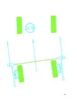
Hang the TR-36 and TR-37 Laser Guns on the front of the vehicle and level them; The 
Laser Guns should snap into place with the laser box facing the rear of the vehicle. 

4)


Set the toe dials on the TR-36, TR-37, TR-38 and TR-39 to zero. 

5)


Adjust the cross laser on the TR-37 to hit the mirror on the TR-36 laser gun. Adjust the toe 
dial on the TR-36 until the cross toe laser beam drops back into the hole on the TR-37 laser 
gun. 

6)


Read the toe dial remembering that the Total Toe is half of what is on the Toe Dial. 

7)


Adjust both toe dials to reflect the Total Front Toe Reading. You now have two parallel 
laser beams going down the sides of the vehicle. 

8)


Set the toe dials on the TR-36 & 37 laser guns to reflect the current toe condition, for 
example 1/16” toe in. 

9)


Notice the laser beams on the combi gauges, the idea here is to have both laser beams on 
the same numbers on both combi gauges.  

10)


To make adjustments for Front Toe you may set the toe dials equally for Total Front Toe. 
For example if the desired toe is 1/8” out, set both toe dials to 1/8” toe out.  

11)


With the steering box locked in the center position loose the tie rods and adjust one tie rod 
HALF the distance back to the hole on the TR-37 laser gun, then adjust the other tie rod the 
other HALF distance back into the hole on the TR-37 laser gun. 

12)


Note the laser beams on the combi gauges, if the left gauge reads 7 and the right gauge 
reads 5. The number for centerline would be 6 (7+5=12 divided by 2 = 6). 

13)


Adjust BOTH tie rods evenly to make the numbers match and the cross toe laser is still in 
the hole. The Two-wheel Centerline alignment is complete when the cross-toe laser is 
reflected off the cross-toe mirror back into the hole and the numbers on the Centering 
scales match.   

Содержание TR-12 Series

Страница 1: ...1 Operating and Service Manual Laser Wheel Alignment System TR 12 Series Race Car Alignment System 8231 Blaine Road Blaine WA 98230 360 371 0552 800 496 3777 Toll Free www Tru Line net...

Страница 2: ...the front and slip plates in the rear to do an alignment Racecars may substitute grease plates for turntables and slip plates No dedicated rack or level surface is required Alignment of vehicles can...

Страница 3: ...Reading the Scales 1 The toe scales are used to dial toe specifications into both Laser Boxes and both Combi Gauges Toe can be measured in millimeters inches or degrees The toe scale is located on the...

Страница 4: ...ther appropriate platform Perform standard pre alignment checks and inspections Remember no alignment can be properly done with loose suspension parts 3 Mount the TR 28 wheel clamps on all four wheels...

Страница 5: ...ettle the suspension Be sure that the front turning plates and rear slip plates are released and move freely 6 Hang the TR 30 on the left front wheel clamp to measure camber caster and SAI a For cambe...

Страница 6: ...12 Remove the Frame Centering Flags 13 Hang the TR 38 and TR 39 on the precision disks which are on either the Hub Adapters or the Rim Clamps which are mounted on the Rear wheels with the mirrors poin...

Страница 7: ...7 LASER BEAM LASER BEAM...

Страница 8: ...CALIBRATION BAR FIGURE 8 First Calibrating the camber of the TR 30 TR 38 and TR 39 Note There is a pivot plate at the end of the TR 40 which has a mounting disc attached to the end a master bubble via...

Страница 9: ...degrees of positive camber you would simply choose the negative five on the scale as your zero 4 Once the camber bubble is zeroed on the camber scale calibration is complete for the camber on that ga...

Страница 10: ...TO R CAMBER ZERO SET TO E SETTING ADJUSTING KNO B TO E SCALE INCHES TO E SCALE DEGREES CAMBER SCALE FRONT RETRO REFLECTO R CAMBER ZERO SET TO E SETTING ADJUSTING KNO B TO E SCALE INCHES TO E SCALE DEG...

Страница 11: ...the Thrust Angle scale on the front of each Laser Gun If the laser reflects back to the hole on the scales then the Laser Gun is calibrated no further adjustment is needed If either of the lasers does...

Страница 12: ...TOE LASER KNO B man1 FIGURE 4 TR 37 RIGHT LASER GUN 1 2 3 4 5 6 7 8 9 GREY ON GREY ON TR 36 LEFT LASER GUN FIGURE 5 9 8 7 6 5 4 3 2 1 man1 REFLECTED CRO SS TO E LASER BEAM PUSH BUTTO N BLACK O FF PUS...

Страница 13: ...ther adjustment is needed If either of the lasers does not reflect back to the hole then follow these steps a Adjust the toe knob of the Combi gauge until the laser returns to the hole on the Thrust A...

Страница 14: ...king on the flag scale Note Attach the measure to the Magnet Mount where it will make contact with the frame Also when using the TR 28 Wheel Clamps it is a good practice to include the clamp in the Fr...

Страница 15: ...now the black side Place the gauge on the black side which is now on the left Read the caster bubble and note the reading 5 Loosen the nut to adjust the height Adjust the screw until the caster bubble...

Страница 16: ...aser beam 4 Remove the Laser Gun and replace it with the TR 51 Calibration Laser Turn on the Cal Laser and point it at the target 5 Move the target so that the laser beam is on a number I E the number...

Страница 17: ...h the slide plate assembly is usually centered for a large diameter wheel you can loosen the locking screws and move the slide plate to the edge of wheel clamp then tighten the locking screws This wil...

Страница 18: ...2 Level the TR 30 using the SAI scale on the top of the post Make sure the TR 30 can move easily so that it stays relatively level when the wheel clamp is rotated 3 Rotate the wheel clamp until the in...

Страница 19: ...a level position with one hand do not grasp or hold tightly rotate the wheel one full turn while watching the caster bubble Here the bubble should not move more than 1 8 of a bubble If the bubble doe...

Страница 20: ...meters is possible By offsetting the center assembly of the TR 28 Wheel Clamp is to accommodate the laser to reach around the oversize tires or low body conditions as seen in the diagram below The Run...

Страница 21: ...cale on each If the vehicle has a front camber greater than 3 degrees use the TR 30 to take the reading Note Any and all adjustments to caster or camber must be made before measuring toe Measuring Cas...

Страница 22: ...scale on the left side is zeroed Note that there is a right and a left zero position of the scale both of which are on the bottom half of the SAI scale Lock the TR 30 in place using the thumbscrew whi...

Страница 23: ...ees in on the scale of the turntable 8 Read the number corresponding to the bubble on the caster scale Record and compare the reading to the factory specifications Left Right 0 0 16 16 8 8 SAI Caster...

Страница 24: ...s 2 Raise wheel and adjust run out using the standard procedure both sides 3 Lower wheel onto turn table and remove locking pin both sides 4 Place TR 44 Level Compensator Bar that has been assembled t...

Страница 25: ...ure compensates for the tilt to give full accuracy caster readings You can measure caster first by following this procedure 1 Place the bar along the side of the vehicle Make sure the ground is reason...

Страница 26: ...26...

Страница 27: ...e TR 36 TR 37 TR 38 and TR 39 to zero 5 Adjust the cross laser on the TR 37 to hit the mirror on the TR 36 laser gun Adjust the toe dial on the TR 36 until the cross toe laser beam drops back into the...

Страница 28: ...28 Note when setting the dial for example to 1 8 it equals a total of 1 8 overall toe or 1 16th on each side LASER BEAM LASER BEAM...

Страница 29: ...back into the hole on the TR 37 laser gun 4 Read the toe dial remembering that the Total Toe is half of what is on the Toe Dial 5 Adjust both toe dials to reflect the Total Rear Toe Reading You now ha...

Страница 30: ...30...

Страница 31: ...laser beam so that it is vertical compensating for the camber Set the toe dial at zero 2 Note the near and far readings on the frame flags If the readings are the same then there is not any toe in the...

Страница 32: ...T section complete the additional procedures to complete a FOUR WHEEL ALIGNMENT Four Wheel Alignment 1 Adjust ALL Toe Dials to the desired setting 2 Make the changes necessary until the laser beam dro...

Страница 33: ...33 LASER BEAM LASER BEAM LASER BEAM 1 2 3 4 5 6 7 8 9 9 8 7 6 5 4 3 2 1 HOW TOE IS MEASURED STEERING WHEEL LOCKED STRAIGHT AHEAD LASER GUN Rear COMBI...

Страница 34: ...enter of the vehicle on the side that is being Offset 4 Level and turn on the Laser Guns so that they are pointing at each other 5 Record the Offset at the Frame Centering Flag and make changes as nec...

Страница 35: ...t its options for the full two years those parts returned to the factory and proves to be defective after inspection by Tru Line This warranty does not cover normal maintenance or adjustment or damage...

Страница 36: ...e and service is not necessary However if the system is not functioning properly the user should not attempt to repair any equipment A Tru Line service representative should perform all servicing and...

Отзывы:

Похожие инструкции для TR-12 Series