Circuit Diagram · Wiring Diagrams
5
Fig 1
Fig 2
Fig 3
Fig 4
N (–)
L (+)
24 V
230 V
50/60 Hz
F
1
b
3
L
4
L
3
L
9
L
7
b
1
L
10
b
4
b
2
B
2
PE
1 2 3 4 5 6 7 8 9 10
4 5 6
1 2 3
1 2 3
1 2 3
1 2 3
1 2 3
L
1
L L N
PE
N
L
1
L L N
PE
N
L
1
L L N
PE
N
L
1
L L N
PE
N
1 2 3 4 5 6 7 8 9 10
L
4
L
4
L
4
L
3
L
3
L
3
B
1
+ –
A
A
A
A
A
The entire electrical installation must be in accordance with VDE
and the local EVU regulations.
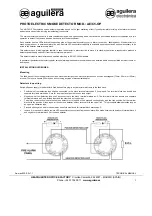
Fig 1
Connection diagram for smoke detector
(fire damper closed)
Fig 2
Installation
without
separate power supply to DC
control device
A
on the fire damper to be controlled,
maximum load: 8 W / 24 V-
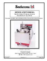
Fig 3
Installation
with
separate power supply for
control device
A
on the fire damper to be controlled,
maximum switched power 250 V / 10 A
or 24 V- / 200 W
Fig 4
Special installation (voltage on to operate principle)
without
separate power supply to AC control device
A
on the fire damper to be controlled,
maximum switched power 250 V / 10 A
L
1
Mains connection 230V 50/60 Hz
L
3
Control device connection (volt-free)
Switched power 250 V / 10 A or 24 V- / 200 W
L
4
Connection of external control max 8 W / 24 V-
Connection for 24 V- external supply:
Residual wave max 2 %;
Consumption min 520 mA;
Without 8 W consumption 190 mA
L
9
– L
9
/1-2 air velocity monitoring (volt-free)*,
– L
9
/3-4 pollution monitoring (volt-free)*,
– L
9
/5-6 system monitoring (volt-free)*
* Switched power 110 V/4 A, 24 V-/100 W
L
7
/L
10
Connection for remote control type T-RM-O-VS or
T-RM-O-VS/1; for remote control, remove link L
7
/1-2
b
1
b
2
Pushbutton test/reset
b
3
b
4
Connection (plug socket) for diagnostic instrument
type D-RM-O-VS
F
1
Fuse 500 mAT
B
1
Link (by others) for connecting
230 V, 50/60 Hz detector
B
2
Link (by others) for connecting
24 V- control device max 8 Watts
A
Control device for fire damper
(AC or DC)
For parallel control
Smoke detector type
type RM-0-VS
Remote control
Type: T-RM-0-VS
Type:
T-RM-0-VS/1
V
elocity
monitor
Smoke alarm