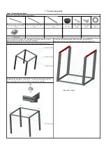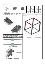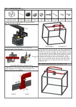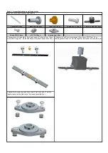
Alu. Profile 2
PM4*20
Sliding rod
Φ8*528 4pcs
Z motor component 2pcs
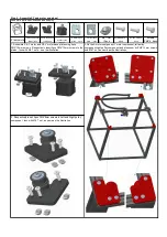
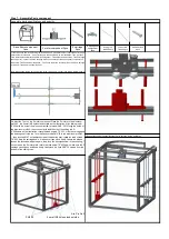
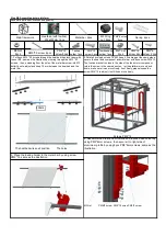
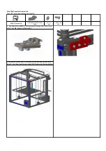
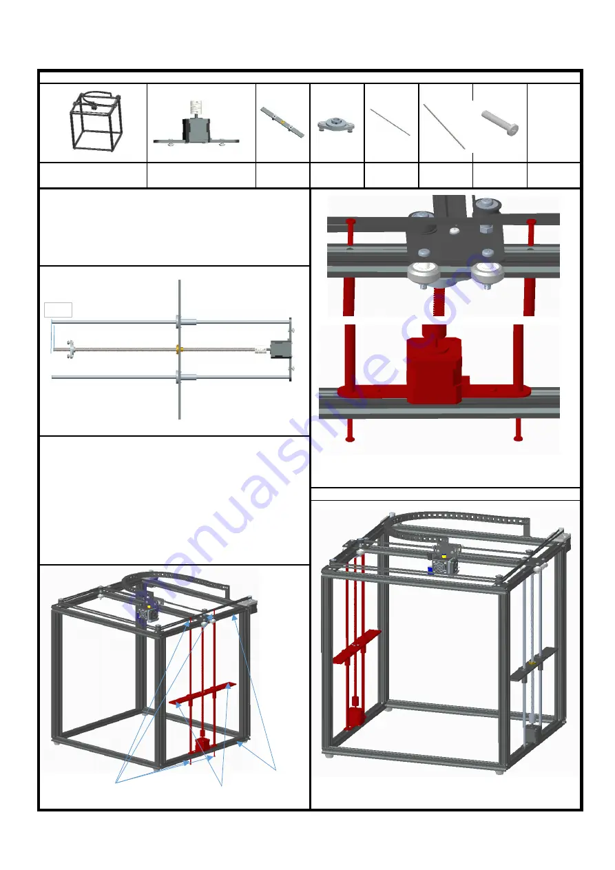
1.Insert the solid end of the Sliding rod to the hole on Z axis motor holder, insert the barrel of the
motor holder into the hole
,
do not let the pole stand out,same as the illustration.Then, put the Z
fixed plate component with the pole Φ8*528 together. Thread the the lead screws T8*453 through
the copper nut, connect with the coupling hole on the motor,put the bearing seat component on
lead screw T8*453 same as illustration
(
The T nuts are at the outer end),then the Z axis carriage
is finished. Total need to assemble 2set.
Lead screw
T8*453 2pcs
Step 7
:
Assemble Z axis component
Assemble parts specifications and quantity
:
Bearing seat
component
2pcs
Screw PM4*20
8pcs
Note:When assemble the pole, keep lead screw T8*453 3mm shorter than sliding rod Φ8*528mm
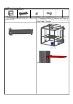
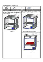
3.Repeat the number 2,assemble other Z aixs carriage, as the illustration.
Z carriage
2pcs
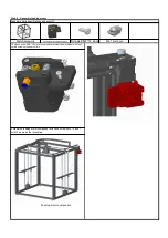
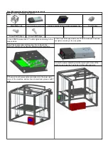
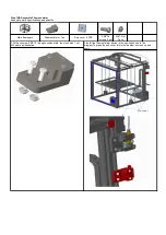
2.Adjust the T nut on the Z motor component, Place the Z motors to the aluminum
profile 2 , the 2 small M3 holes stand outsite as the illustration. Align sliding rod Φ
8*528 with the hole of the aluminum profile, let screw PM4 * 20 through the holes of
the aluminum profile 2, then connect with the M4 hole of the sliding rod Φ
8*528,same as the illustration, rotate the lead screws T8*453
,
slide the carriage and
the bearing seat to the top, lock the 2pcs screws PM4*20 to the aluminum profile 2
,
then lock the M4 T nut and jackscrew of the bearing seat, rotate the lead screws
T8*453, drop the carriage down
,
make sure it can move freely. Otherwise, please
loosen the jackscrew,adjust it again. then, lock the 4pcs jackscrew in the coupling , T
nut, screw on the Z motor plate, rotate the lead screw T8*453 again,make sure the Z
carriage can slide up and down freely. finally lock the 2pcs PM4*20 screws from the
bottom of the sliding rods .
Base frame component
1pcs
2 small M3 holes stand outside
3mm


