11
ASSEMBLY STEPS
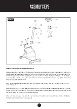
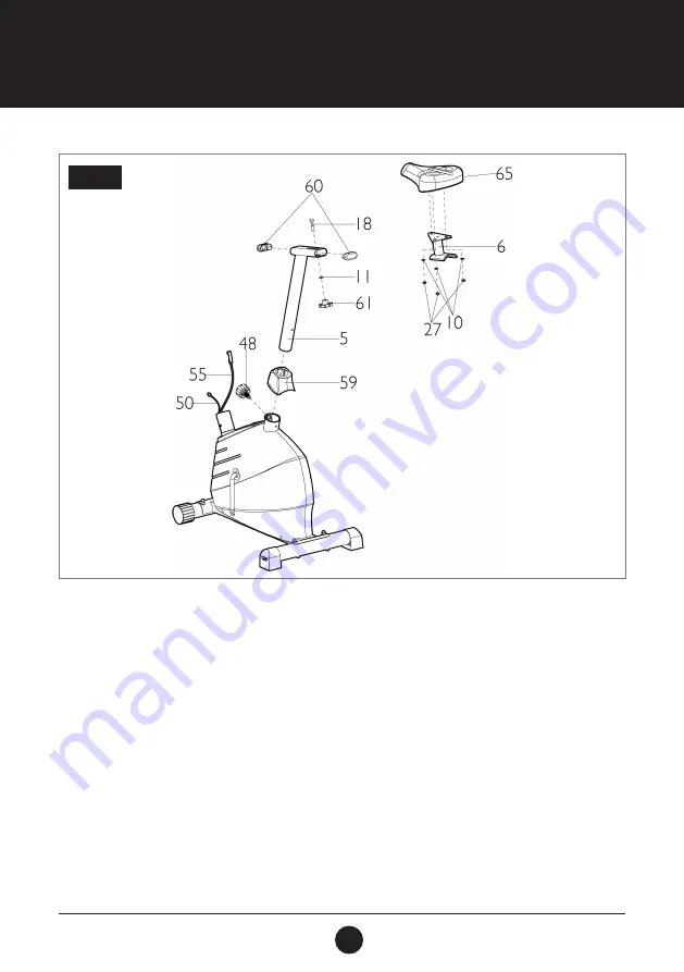
STEP 2: THE UP-RIGHT POST ASSEMBLY
Release the Locking Knob (48) by turning it in a counterclockwise direction until it can be pulled out. Pull out the
Locking Knob (48) and slide the Seat Post (5) into the Bushing (53) and Seat Post Cover (59) on the tube of the
Main Frame (1). Lock the Seat Post (5) in place by releasing the Locking Knob (48) and sliding the Seat Post (5) up
or down slightly until the Locking Knob (48) clicks into the locked position. For added safety, tighten the Locking
Knob (48) in a clockwise direction.
NOTE: When adjusting the height of seat post, the maximum insert depth mark line cannot be higher than the
edge of the post.
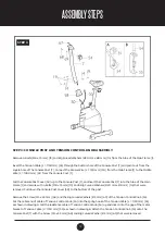
Remove 3 Nuts (M8) (27) and Washer (Ø16 mm x Ø8 mm) (10) from underneath the Seat (DD-982GELT) (65) and
then attach the Seat (DD-982GELT) (65) onto the triangle plate of Seat Sliding Tube (6) with 3 Nuts (M8) (27) and
3 Washers (Ø16 mm x Ø8 mm) (10) that were removed.
Attach the Seat Sliding Tube (6) onto the Seat Post (5) with a Washer (Ø20 mm x Ø10 mm) (11), Nut (M10) (61),
Bolt (M10 x 50 mm) (18) and 2 End Caps (60).
STEP 2
Содержание PACE 380
Страница 9: ...9 EXPLODEDDRAWING...


