13
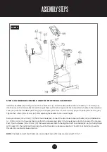
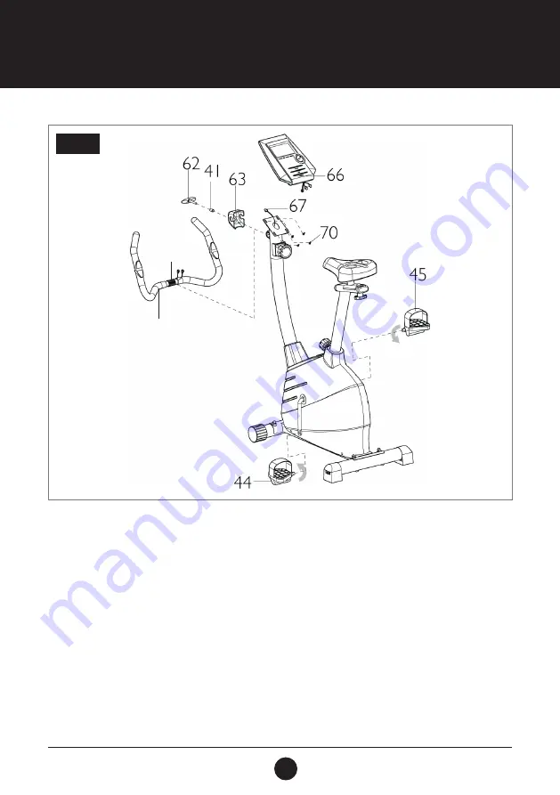
STEP 4: HANDLEBAR, CONSOLE AND THE FOOT PEDALS ASSEMBLY
Install the Handlebar (8) to the groove of the Console Post (7). Insert the Hand Pulse Sensor with Wires (L = 750 mm) (49)
into the hole on the Console Post (7) and then pull them out from the top end of the Console Post (7). Attach the Decorative
Cover (63) onto the Handlebar (Ø25 mm) (8) with a Spacer (Ø12 mm x 1.5 mm x 20 mm) (41) and T-Knob (M8 x 55 mm) (62).
Tighten the T-Knob (M8 x 55 mm) (62) after adjusting the handles to the correct height.
Remove 4 Screws (M5 x 10 mm) (70) from the Console (66). Connect the Hand Pulse Sensor with Wire (49) and Middle Wire
(L = 1000 mm) (67) to the wires that come from the Console (66). Attach the Console (66) onto the top end of the Console
Post (7) with 4 Screws (M5 x 10 mm) (70) that were removed. Attach the Right and Left Foot Pedals (45, 44) to the Right and
Left Cranks (39). The Right Foot Pedal (45) should be threaded in a clockwise direction. The Left Foot Pedal (44) should be
threaded in a counterclockwise direction.
NOTE:
The Right and Left Foot Pedals (45, 44) and Right and Left Cranks are marked with “R” & “L”.
STEP 4
ASSEMBLY STEPS
49
8
Содержание PACE 380
Страница 9: ...9 EXPLODEDDRAWING...


