Triton TPL180 Скачать руководство пользователя страница 7

7

GB

Adjusting the depth of cut

Note: 

The Power Indicator (2) lights up when the tool is connected to a live mains supply.  

This is a quick indicator of a live power connection to the tool for normal use but it is  
important also to check manually that the power tool is disconnected from the mains when 
making adjustments or installing or removing blades.
1.  Rotate the Depth Adjustment Knob (12) clockwise for a deeper cut and anti-clockwise for 

a shallower cut

2.  The numbers on the ring under the Depth Adjustment Knob indicate the depth of cut.  

There are 8 click stop positions from 0.25-2mm that increment by 0.25mm

3.  If it is necessary to plane to a precise depth, plane a scrap piece of wood, measure the 

difference in thickness and adjust the setting if necessary 

4.  To check accuracy and tolerance of the Movable Front Base (11) set the depth adjustment 

knob to the ‘0’ position so the blade can be measured against the Fixed Rear Base (6) and 
Movable Front Base (11). The Fixed Rear Base, blade and Movable Front Base should be at 
the same level at the ‘0’ position

5.  After use, always move the depth adjustment knob to the ‘P’ parked position. This protects 

the blade by moving the Movable Front Base so that the blade is not in contact with the 
surface the planer is resting on

Operation

Switching ON & OFF

 WARNING:

 Before plugging the machine into the mains power point always check that 

the On/Off Trigger Switch (3) and Trigger Safety Lock (4) work properly. Before switching on, 
ensure that the blade drum or blade is not making contact with any surface.
1.  Plug in the machine, push in the Trigger Safety Lock (4) (Image G) and pull the ON/OFF 

Trigger Switch (3) (Image H)

2.  Stop the tool by simply releasing the ON/OFF Trigger Switch
3.   In order to restart the machine, it is necessary to operate both the Trigger Safety Lock (4) 

and the ON/OFF Trigger Switch (3). This is an important safety feature that helps prevent 
accidental operation of the planer

CAUTION:

 Please note that the planer blades continue to spin for some time after switching off 

the planer. Wait until the motor has completely stopped before setting down the tool to prevent 
damage to the planer blades or the surface.
•  If resting the planer on its side, do not rest it on the vented side. This will prevent dust or 

chips from contaminating the motor

•  When the planer is not to be used for a short period, set the depth control knob to the ‘P’ 

(parked) position and ensure both bases (6) and (11) are resting on the same level surface

Planing

1.  Rest the Movable Front Base (11) flat on the workpiece surface without the blades making 

any contact with the workpiece

2.  Switch on the tool and wait for the blades to reach full speed
3.  Move the tool gently forward, applying pressure on the front of the tool, using one hand on 

the Front Handle (1) at the start of planing. Apply pressure at the rear of the tool using the 
other hand on the Main Handle (5) towards the end of the planing stroke

Note: 

It is important to understand that the Movable Front Base dictates how much of the 

blade is exposed to the wood and this requires the user to apply downward pressure on both 
the front and back of the tool evenly during use.
4.  Push the planer beyond the edge of the workpiece without tilting it downwards or upwards

Tip: 

Treat the material as if it is slightly longer than it actually is - the planing action will 

continue until the blades have well passed the end of the workpiece.
5.  The rate of planing and the depth of cut determine the quality of the finish. For rough 

cutting, the depth of cut can be increased; however to achieve a good finish, the depth of 
cut should be reduced and the tool advanced more slowly

Note:

 Planing is easier if the workpiece is inclined slightly away from the operator so that 

planing is performed ‘downhill’. 

WARNING: 

The planer is very heavy and not practical or safe to be used for vertical planing or 

other similar applications.

CAUTION:

 Moving the machine too fast may cause a poor quality of cut and can damage the 

blades or the motor. Moving the machine too slowly may burn or mark the cut
•  The proper feed rate will depend on the type of material being cut and the depth of the cut
•  Practise first on a scrap piece of material to gauge the correct feed rate and the cut 

dimensions

CAUTION: 

Always use two hands to hold the planer

CAUTION:

 Where possible, clamp the workpiece to the bench

Chamfering 

1.  To perform a chamfered cut as shown in (Fig. I), first align the ‘v’ groove (Fig. II) in the 

Movable Front Base (11) of the planer with the corner edge of the workpiece.

2.  Run the planer along the corner edge.

Maintenance


WARNING: 

Always ensure that the tool is switched off and the plug is removed from the 

mains power point before making any adjustments or maintenance procedures. 
•  Inspect the supply cord of the tool, prior to each use, for damage or wear. Repairs should 

be carried out by an authorised Triton service centre. This advice also applies to extension 
cords used with this tool

Regularly check that all the fixing screws are tight. They may vibrate loose over time.

Cleaning

1.  Keep the tool’s air vents unclogged and clean at all times
2.  Remove dust and dirt regularly. Cleaning is best done with compressed air or a dry,  

soft-to-medium brush like a paint brush

CAUTION:

 Wear protective goggles when cleaning the tool.

3.  Re-lubricate all moving parts at regular intervals
4.  Never use caustic agents to clean plastic parts

CAUTION:

 Do not use cleaning agents to clean the plastic parts of the tool. A mild detergent on 

a damp cloth is recommended. Water must never come into contact with the tool. Ensure the 
tool is thoroughly dry before using it.

Removing & installing planer blades  


WARNING

: Ensure the blade Clamping Screws (16) are tightened securely in the correct 

order shown in image M. Incorrect and/or insufficient tightening could cause serious injury 
to the operator.
This planer is fitted with HSS reversible blades. Blades can be reversed when blunt. After both 
sides of the blades have been used they should be discarded.

 WARNING

: These blades cannot be re-sharpened.

Removing a planer blade

CAUTION:

 The blades are very sharp. Take care when handling them

1.  Using the supplied Blade Spanner (17), loosen the 5 Clamping Screws (16) (Image I)
2.  Line up the Blade Barrel (14) with the side indentation so the required Reversible Blade 

(15) can be removed, then carefully slide out the blade (Image J)

Installing a planer blade


WARNING

: Only use HSS planer blades compatible with this tool. Using incorrect blades 

that are not HSS could cause serious injury to the operator.
1.  The blades are reversible with a cutting edge on both sides. If a blade edge is worn or 

damaged, the blade can be removed and placed back the other way around

2.  Slide a good blade face up into the blade support block of the Blade Barrel (14)

Note:

 If only one blade is damaged, it can be replaced without the need to replace the 

other two blades. When blades are worn, they must be replaced as a set of three to prevent 
unbalanced operation with consequential dangerous vibration and possible damage to the tool

Note:

 The ridge along the blade should be on the blade face on the opposite side to the 

Clamping Screws (16).

When installing blades:

1.  First clean out all chips or foreign matter adhering to the Blade Barrel (14) and the  

blades themselves 

2.  Use blades of the same dimensions and weight, or the barrel will oscillate and vibrate 

causing poor planing action and possibly a machine breakdown 

3.  Tighten the Clamping Screws (16) in the order shown in Image M when attaching the 

blades to the planer. A loose clamping screw could be extremely dangerous 

4.  Tighten to a torque value of 10Nm (±0.5); do not over-tighten
5.  Repeat for the two remaining blades
6.  Regularly check to see they are tightened securely

IMPORTANT:

 Once all adjustments have been made to the blades, it is important to re-check 

that the clamping screws are secure. After a short period of work activity check that they 
remain tight and at a torque value of 10Nm (±0.5). Carry out another check after a reasonable 
period of use.

IMPORTANT: 

The planer is designed so that the blades are correctly aligned if placed flush into 

the barrel slots and tightened correctly.
•  When inserting new blades it is essential they sit square in their slot; that they are fully 

inserted; and that the cutting edges are absolutely level, i.e. parallel to the surface of 
the rear base 

•  A metal ruler can be placed on the rear base at 3 different positions to ensure the blade 

is level 

•  Only when the blade is level with the rear base should the clamping screws be tightened
•  A further check of the Movable Front Base (11) position can be made by setting the Depth 

Adjustment Knob (12) to ‘0’ and placing the ruler across both the Movable Front Base 
and Rear Fixed Base (6) (Image K). This provides a reference to the accuracy of the front 
base position

•  Blade must be positioned centrally on the drum (Image L) 

WARNING:

 If the blades protrude or are not square, they could hit the casing with serious risk 

to the operator and others in the vicinity.

Note: 

The planing surface will end up rough and uneven unless the blades are set and  

secured properly.

366649_Manual.indd   7

20/02/2019   10:22

Содержание TPL180

Страница 1: ...e Seguran a Instructions d utilisation et consignes de s curit Instrukcja obs ugi i bezpiecze stwa Gebrauchs und Sicherheitsanweisung Istruzioni per l uso e la sicurezza Kezel si s biztons gi utas t...

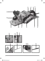
Страница 2: ...2 2 3 5 4 1 12 6 7 9 10 11 8 13 21 20 17 19 18 14 15 16 366649_Manual indd 2 20 02 2019 10 22...

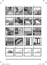
Страница 3: ...3 A E I M II B F J N III C G K IV D H L I V VI 5 1 2 3 4 366649_Manual indd 3 20 02 2019 10 22...

Страница 4: ...ymbols The rating plate on your tool may show symbols These represent important information about the product or instructions on its use Thank you for purchasing this Triton tool This manual contains...

Страница 5: ...y other condition that may affect the power tool s operation If damaged have the power tool repaired before use Many accidents are caused by poorly maintained power tools f Keep cutting tools sharp an...

Страница 6: ...eed work into the blade or cutter against the direction of movement of the blade or cutter Beware of heat Cutting tools and workpieces may become hot in use Do not attempt to change tools until they h...

Страница 7: ...11 of the planer with the corner edge of the workpiece 2 Run the planer along the corner edge Maintenance WARNING Always ensure that the tool is switched off and the plug is removed from the mains po...

Страница 8: ...s caused by the edge of one or all blades protruding too far in relation to the surface of the rear base Fig VI a Movable Front Base 11 which is altered by the Depth Adjustment Knob 12 b Fixed Rear Ba...

Страница 9: ...ply This does not affect your statutory rights oves to be defecti Notified body T V Rheinland Co Ltd The technical documentation is kept by Triton Tools Date 20 06 2018 Signed Mr Darrell Morris Managi...

Страница 10: ...Stofontginning vereist of aanbevolen Beschermingsklasse II dubbel ge soleerd Voldoet aan de relevante wetgeving en veiligheidsnormen Milieubescherming Elektrische producten mogen niet met het normale...

Страница 11: ...hap niet als de schakelaar van het apparaat niet in en uitschakelt Elektrisch gereedschap dat niet bediend kan worden met de schakelaar is gevaarlijk en moet gerepareerd worden c Haal de stekker uit h...

Страница 12: ...en die zijn aanbevolen voor uw machine Probeer zaaggereedschap niet te wijzigen Zorg ervoor dat de bladen scherp zijn in goede staat verkeren en juist gemonteerd zijn Bladen die niet te slijpen zijn w...

Страница 13: ...van de machine brand of markeert mogelijk de schaafsnede De juiste snelheid hangt af van het te schaven materiaal en de schaafdiepte Oefen op een stuk afvalmateriaal voor de juiste schaafsnelheid en...

Страница 14: ...ven schaafoppervlak De voorbeelden laten juiste en onjuiste instellingen zien Juiste instelling Soepele fijne schaafsnede Fig III Inkepingen in het werkstuk n of meerdere schaafbladranden liggen niet...

Страница 15: ...0 dagen Algemene voorwaarden van toepassing Keuringsinstantie T V Rheinland Co Ltd De technische documentatie wordt bijgehouden door Triton Tools Datum 20 06 2018 Handtekening Darrell Morris Algemeen...

Страница 16: ...etenu mal assembl ou mal utilis peut augmenter les niveaux sonores et vibratoires Pour plus d informations sur la directive des missions sonores et vibratoires visitez le site http osha europa eu fr P...

Страница 17: ...me pour lequel il a t con u permettra de r aliser un travail de meilleure qualit et dans de meilleures conditions de s curit b Ne pas utiliser un outil lectrique dont l interrupteur marche arr t est h...

Страница 18: ...Dans certains cas des d bris peuvent tre projet s de l outil de coupe grande vitesse Assurez vous qu aucune autre personne ne se trouve proximit de la zone de travail Si la pr sence d autres personnes...

Страница 19: ...de travail sans l incliner que ce soit vers le haut ou vers le bas Conseil Faites comme si la pi ce de travail tait l g rement plus longue De cette fa on vous sortirez les fers de la pi ce de travail...

Страница 20: ...de profondeur 12 sur 0 et en pla ant un r glet travers la semelle avant mobile et la semelle arri re fixe Image K Cela donne galement une indication de la pr cision de la semelle avant Blade must be...

Страница 21: ...ligne dans les 30 jours suivant la date d achat Offre soumise conditions Ceci n affecte pas vos droits statutaires Organisme notifi T V Rheinland Co Ltd La documentation technique est conserv e par T...

Страница 22: ...ischen Daten des jeweiligen Werkzeuges und bestimmen Sie die zul ssige Belastungsdauer und h ufigkeit Geh rschutz tragen Augenschutz tragen Atemschutz tragen Kopfschutz tragen Schutzhandschuhe tragen...

Страница 23: ...inen sicheren Stand und halten Sie jederzeit das Gleichgewicht Auf diese Weise l sst sich das Elektrowerkzeug in unerwarteten Situationen besser kontrollieren f Tragen Sie geeignete Kleidung Tragen Si...

Страница 24: ...ereich keinen gef hrlichen Schallpegeln oder Staub ausgesetzt werden Sorgen Sie daf r dass diesen Personen geeignete Schutzausr stung zur Verf gung steht Nicht sichtbare Gegenst nde Untersuchen Sie da...

Страница 25: ...sperre 4 erneut zu entriegeln bevor der Ausl seschalter 3 gedr ckt werden kann Hierbei handelt es sich um eine wichtige Schutzeinrichtung die ein versehentliches Einschalten der Maschine verhindert AC...

Страница 26: ...e sitzen Die Klemmschrauben d rfen erst angezogen werden wenn die Messer korrekt ausgerichtet sind und ihr korrekter Sitz berpr ft worden ist Eine weitere berpr fung der Position der verschiebbaren vo...

Страница 27: ...wenn nicht anders angewiesen in unseren elektronischen Verteiler aufgenommen damit Sie Information ber zuk nftige Produkteinf hrungen erhalten Die von Ihnen bereitgestellten Angaben werden nicht an D...

Страница 28: ...ia prima di eseguire la manutenzione e quando non in uso NON utilizzare in caso di pioggia o in ambienti umidi Attenzione Aspirazione polveri richiesto o consigliata Classe II di costruzione doppio is...

Страница 29: ...no essere riparati immediatamente c Staccare la spina dalla presa di corrente prima di effettuare qualsiasi regolazione sostituire gli accessori o riporre gli attrezzi a motore Queste misure di sicure...

Страница 30: ...Attenzione ai rifiuti proiettati In alcune situazioni i rifiuti possono essere proiettati a velocit da taglio Assicurarsi che non ci siano altre persone all interno dell area di lavoro Se necessario...

Страница 31: ...a e la profondit di taglio determinano la qualit della finitura Per un taglio grezzo la profondit di taglio pu essere aumentata Tuttavia per ottenere una buona finitura la profondit di taglio deve ess...

Страница 32: ...e sporgono o non sono quadrati potrebbero colpire l involucro con grave rischio per l operatore e gli altri nelle vicinanze NB La superficie della piallatura finir ad essere ruvida e irregolare a meno...

Страница 33: ...incidenti abuso o uso improprio Registrati entro 30 giorni Si applicano termini e condizioni Ci non pregiudica i diritti legali Organismo informato T V Rheinland Co Ltd La documentazione tecnica mante...

Страница 34: ...normal de la herramienta en condiciones normales Una herramienta defectuosa mal montada o desgastada puede incrementar los niveles de ruido y vibraci n Para m s informaci n sobre ruido y vibraci n pu...

Страница 35: ...la bater a antes de realizar cualquier ajuste cambiar accesorios o almacenar la herramienta Estas medidas de seguridad preventivas evitar n el arranque accidental de su herramienta el ctrica d Guarde...

Страница 36: ...r Atenci n al material que sale despedido En algunas situaciones el material puede salir despedido de la herramienta de corte a gran velocidad Aseg rese de que no haya otras personas en la zona de tra...

Страница 37: ...ncipal 5 Nota La base frontal ajustable 11 representar la cantidad en la que la cuchilla est expuesta esto requerir aplicar presi n en ambos extremos de la herramienta durante el funcionamiento 4 Empu...

Страница 38: ...a regla a trav s de la base frontal ajustable 11 y la base posterior fija 6 Imagen K Esto le servir como gu a para ajustar la base frontal de forma precisa La cuchilla debe de estar correctamente cent...

Страница 39: ...ntados a partir de la fecha de compra Se aplican los t rminos y condiciones Esto no afecta a sus derechos legales como consumidor Organismo notificado T V Rheinland Co Ltd La documentaci n t cnica se...

Страница 40: ...o estiver em uso N O use sob chuva ou em ambientes midos Cuidado Coleta de p necess ria ou recomendada Constru o de classe II isolamento duplo para prote o adicional Cumpre a legisla o e os padr es d...

Страница 41: ...onecte o conector de tomada da rede el trica e ou a bateria da ferramenta antes de realizar quaisquer ajustes trocar acess rios ou de guard la Estas medidas de seguran a preventivas reduzem o risco de...

Страница 42: ...st o afiadas em boas condi es e corretamente instaladas N o tente afiar as l minas que n o forem indicadas para isso Incluem se nesse caso l minas especialmente endurecidas ou l minas feitas de ligas...

Страница 43: ...corte mais bruto entretanto para conseguir um acabamento melhor a profundidade do corte dever ser reduzida e a ferramenta avan ar mais devagar Nota O aplainamento ser mais f cil de executar se a pe a...

Страница 44: ...fundidade 12 em 0 e colocando uma r gua sobre ambas as bases frontal m vel e traseira fixa 6 Figura K Isto ir fornecer uma refer ncia para a precis o da posi o da base frontal A l mina deve ser posici...

Страница 45: ...nline dentro de 30 dias ap s a compra Termos e condi es aplic veis Isto n o afeta seus direitos legais Org o notificado T V Rheinland Co Ltd A documenta o t cnica mantida pela Triton Tools Data 20 06...

Страница 46: ...ziem Nale y nosi rodki ochrony s uchu Nale y nosi okulary ochronne Nale y nosi rodki ochrony dr g oddechowych Nale y u ywa kasku ochronnego Nale y nosi r kawice ochronne Nale y w ca o ci przeczyta ins...

Страница 47: ...ej chwili zachowuj odpowiedni pozycje i r wnowag Umo liwia to lepsz kontrol nad elektronarz dziem w nieoczekiwanych sytuacjach f No odpowiedni odzie Nie zak adaj do pracy z elektronarz dziem lu nej od...

Страница 48: ...i brakuje pewnych cz ci lub s one uszkodzone nale y uzupe ni lub wymieni je przed rozpocz ciem korzystania z narz dzia Przygotowanie OSTRZE ENIE Upewnij si e urz dzenie jest od czone od zasilania prze...

Страница 49: ...zotk o redniej twardo ci w kszta cie p dzla UWAGA Podczas czyszczenia urz dzenia no okulary ochronne 3 Nale y regularnie smarowa wszystkie elementy ruchome narz dzia 4 Do czyszczenia element w plastik...

Страница 50: ...u u ytkowania Przyk ady zamieszczone poni ej przedstawiaj ustawienie prawid owe i nieprawid owe Ustawienie prawid owe czyste g adkie ci cie Rys III Wci cia w powierzchni materia u spowodowane przez kr...

Страница 51: ...wania Powy sze postanowienia nie maj wp ywu na prawa ustawowe klienta Jednostka notyfikowana T V Rheinland Co Ltd Dokumentacja techniczna produktu znajduje si w posiadaniu Triton Tools Data 20 06 2018...

Страница 52: ...E PT E 52 RU II 230 50 1500 15 000 0 2 180 3 180 525 x 275 x 170 8 6 Triton LPA 94 LWA 105 K 3 5 8 2 7 0 2 1 5 2 85 Triton B a c A mA n0 n d c 1 rpm 2 85 366649_Manual indd 52 20 02 2019 10 22...

Страница 53: ...E PT E 53 RU EN60745 www osha europa eu 1 a 2 a 3 a 4 a 30 5 a 366649_Manual indd 53 20 02 2019 10 22...

Страница 54: ...E PT E 54 RU 30 1 2 3 4 5 6 7 8 200 9 10 11 12 13 14 85 366649_Manual indd 54 20 02 2019 10 22...

Страница 55: ...5 6 7 4 8 9 10 4 11 12 13 14 15 16 5 17 18 19 20 21 2 1 9 1 2 13 1 20 21 7 10 D 2 3 1 18 2 19 F 3 2 1 12 2 0 25 2 0 25 8 3 4 11 0 6 11 0 5 3 4 1 4 G 3 2 E 3 3 4 6 11 1 11 2 3 1 5 4 366649_Manual indd...

Страница 56: ...E PT E 56 RU 5 1 I V 11 II 2 Triton 1 2 3 4 16 1 5 16 17 I 2 14 16 J 1 2 14 16 1 14 2 3 16 4 10 0 5 5 16 10 0 5 3 11 12 0 6 L III IV V VI 11 12 b 6 1 8 N 2 3 4 366649_Manual indd 56 20 02 2019 10 22...

Страница 57: ...l Limited Company No 06897059 Powerbox Boundary Way Lufton Trading Estate Yeovil Somerset BA22 8HZ United Kingdom CE Darrell Morris Triton Tools TPL180 180 1500 2006 42 EC 2014 30 EC 2011 65 EU EN 607...

Страница 58: ...zabad a h ztart si hullad kba dobni K rj k vigye el a megfelel jrafelhaszn l si helyre ha l tezik ilyen Keresse meg a helyileg illet kes hat s gokat vagy a forgalmaz t az jrafelhaszn l sra vonatkoz ta...

Страница 59: ...Ker lje a rendellenes testtart st Mindig biztosan lljon a l b n s rizze meg az egyens ly t Ez az elektromos k ziszersz m biztosabb ir ny t s t teszi lehet v v ratlan helyzetekben f lt zz n megfelel en...

Страница 60: ...jon megfelel nyom rudat a r videbb munkadarabok elektromos k ziszersz mmal t rt n megmunk l sakor gyeljen a k rnyezet ben l v szem lyekre A szersz m haszn l j ra h rul annak biztos t sa hogy a munkate...

Страница 61: ...a gyalu fekszik Haszn lat Be s kikapcsol s FIGYELEM Miel tt csatlakoztatja a g pet a t pfesz lts ghez mindig ellen rizze hogy a Be Ki ravaszkapcsol 3 s a ravaszkapcsol biztons gi reteszel gombja 4 hib...

Страница 62: ...yeges hogy az j k sek mer legesen helyezkedjenek el a ny l saikban teljesen a hely kre legyenek tolva s v g leik t k letesen szintben legyenek azaz p rhuzamosak legyenek a h ts talp fel let vel A k s...

Страница 63: ...k sz b lni forduljon a hivatalos Triton m rkaszervizhez J t ll s A j t ll s regisztr l s hoz l togassa meg webhely nket a www tritontools com c men s adja meg adatait Adatai beker lnek a levelez si li...

Страница 64: ...u a kdy n ad nepou v te Nepou vejte p i de ti nebo ve vlhk m prost ed Pozor Vy aduje nebo se doporu uje ods v n prachu T da ochrany II dvojit izolace pro vy ochranu V souladu s p slu nou legislativou...

Страница 65: ...nebo odstra te akumul tor Toto preventivn opat en zabr n ne mysln mu zapnut elektron ad d Uchov vejte nepou van elektron ad mimo dosah d t Nenechte stroj pou vat osob m kter se strojem nejsou sezn me...

Страница 66: ...osti vym te je Pokud p ijde ost do kontaktu s materi lem pro kter nen ur eno okam it ost vym te Sm r vstupu materi lu Materi l v dy pod vejte proti sm ru pohybu fr zy nebo kotou e D vejte pozor na tep...

Страница 67: ...an 1 Abyste mohli prov d t sr en hran jako je uk z no na obr zku I nasa te hobl k dr kou tvaru V obr zek II na pohybliv p edn z kladn 11 na hranu materi lu 2 Ve te hobl k pod l t to hrany dr ba VAROV...

Страница 68: ...oblovan ho materi lu bude hrub a nerovn dokud nebudou no e spr vn usazeny a p ipevn ny P klady n e ukazuj spr vn a nespr vn nasazen Spr vn nasazen ist jemn ez obr III Z ezy v povrchu v pr b hu hoblov...

Страница 69: ...o prohl en je v souladu s p slu nou harmoniza n legislativou Unie V robek slo TPL180 Popis Triton hobl k se t emi no i 1500 W 180 mm Byl uveden na trh ve shod se z kladn mi po adavky a p slu n mi usta...

Страница 70: ...zpe nostn mi tandardmi Ochrana ivotn ho prostredia Nevyhadzujte elektron radie do domov ho odpadu Zariadenie odovzdajte na recykl ciu V pr pade ot zok kontaktujte pr slu n rad alebo predajcu Typov t t...

Страница 71: ...jsou p ipojeny a spr vn pou ity Pou it ods v n prachu m e sn it ohro en prachem 4 Sv domit zach zen a pou v n elektron ad a P stroj nep et ujte Pro svou pr ci pou ijte k tomu ur en elektron ad S vhod...

Страница 72: ...roj je ostr v dobrom stave a spr vne uchyten Nepok ajte sa ostri rezn n stroje ktor nie s ur en na opakovan ostrenie tak n stroje m u ma peci lne tvrden ostrie ktor je vyroben z tvrd ch zliatin obsahu...

Страница 73: ...iahli dobr ch v sledkov je lep ie zmen i h bku odoberanej vrstvy a pohybova hobl kom pomal ie Pozn mka Hob ovanie je jednoduch ie ak materi l tro ku naklon te smerom od v s hob ujete potom akoby smero...

Страница 74: ...rolu pohyblivej prednej z kladne 11 m ete nastavi koliesko nastavenia hr bky odoberanej vrstvy 12 na 0 Potom polo te prav tko cez obe z kladne predn aj zadn 11 a 6 Skontrolujete tak presnos nastavenia...

Страница 75: ...v robcu Predmet tohto vyhl senia je v s lade s pr slu nou harmoniza n legislat vou nie V robok slo TPL180 Popis Triton hobl k s tromi no mi 1500W 180mm Bol uveden na trh v s lade so z kladn mi po iada...

Страница 76: ...ellerinizin s cakl normal rahat bir s cakl n alt nda oldu u zaman el aleti kullanmay n Spesifikasyonda titre im ile ilgili olarak verilmi de erleri kullanarak el aletini al t rma s resini ve s kl n h...

Страница 77: ...kli el aleti tehlikelidir ve tamir edilmelidir c Elektrikli el aletlerinde ayar yapmadan aksesuarlar de i tirmeden veya saklamadan nce aletin fi ini g kayna ndan ve veya batarya grubundan ekin Bu gibi...

Страница 78: ...ay n bunlar n aras nda zel olarak sertle tirilmi b aklar veya genelde volfram i eren sertle tirilmi ala mlardan olu an b aklar yer alabilir Bileylenebilecek b aklar yaln zca reticinin talimatlar na uy...

Страница 79: ...tin n ne ve arkas na e it bir ekilde a a y nl bas n uygulamas gerekti ini anlamak nemlidir 4 Planya makinesini a a veya yukar do ru itmeden i par as n n ucunun tesine itin pucu Materyali normal uzunlu...

Страница 80: ...sabitlenmezse planyalanan y zey p r zl ve e ri olur A a udaki rnekler uygun olan ve uygun olmayan yerle tirmeleri g stermektedir Do ru yerle tirme temiz p r zs z kesim ek III Y zeyde entikler b aklard...

Страница 81: ...e ileti ime ge in Garanti Garantinizi tescil ettirmek i in www tritontools com adresindeki web sitemizi ziyaret ederek bilgilerinizi giriniz Size ait bilgiler ilerideki yay nlar hakk nda bilgi vermek...

Страница 82: ...366649_Manual indd 82 20 02 2019 10 23...

Отзывы: