


9
Extender Kit Installation
(B130-101A-MR and B130-101A-SR)
Note:
1. If desired, perform the EDID copy procedure described in this manual prior to
installation.
2. Test to make sure the entire installation works properly before pulling cables
through ceilings/walls.
3. To achieve maximum distance and performance, 24 AWG solid-wire Cat5e/6
cable must be used. The use of stranded wire Cat5e/6 cable, or cable with a
gauge (AWG) size higher than 24 AWG will result in shorter extension distance.
All Tripp Lite N202-Series cables are made with 24 AWG solid-wire cabling.
Tripp Lite N022-01K-GY (Cat5e) and N222-01K-GY (Cat6) are 24 AWG solid-wire
bulk cables. For optimal image quality, use Zero-Skew cable such as Tripp Lite
P524-01K.
1
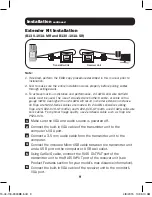
Make sure the VGA and audio source is powered off.
2
Connect the built-in VGA cable of the transmitter unit to the
computer’s VGA port.
3
Connect a 3.5 mm audio cable from the transmitter unit to the
computer.
4
Connect the included Micro USB cable between the transmitter unit
and a USB port on the computer or USB wall outlet.
5
Using Cat5e/6 cable, connect the RJ45
OUTPUT
port of the
transmitter unit to the RJ45
INPUT
port of the receiver unit (see
Product Features section for your model’s max distance information).
6
Connect the built-in VGA cable of the receiver unit to the monitor’s
VGA port.
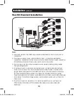
Installation
continued
Transmitter Unit
Receiver Unit
15-04-118-9333BE.indd 9
4/8/2015 10:35:10 AM


