


14
1
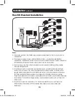
Make sure that the VGA and audio source is powered off.
2
Connect the VGA and audio source to the
INPUT
port(s) on the
transmitter unit using a VGA and audio cable.
3
Using the included daisy chain cable, connect the
LOCAL
port(s) on
the transmitter unit to the
INPUT
ports on a second-level transmitter
unit.
Note:
A standard VGA cable can be used to increase the distance between
units by no more than 6 ft.
4
Repeat step 3 for each additional transmitter unit you are adding to
the daisy chain, with no more than 6 transmitter units in the entire
installation.
5
(Optional) –
Connect a local monitor and speakers to the
LOCAL
port(s) of the last transmitter unit in the daisy chain using a VGA and
audio cable.
6
Connect the external power supply to the first transmitter unit in the
installation, and then plug it into a Tripp Lite Surge Protector, Power
Distribution Unit (PDU) or Uninterruptible Power Supply (UPS).
7
Repeat step 6 for each additional transmitter unit in the installation.
8
Using Cat5e/6 cable, connect an available RJ45
OUTPUT
port on
the transmitter unit to the RJ45
INPUT
port on a receiver unit (see
Product Features section for your model’s max distance information).
9
Repeat step 8 for each receiver unit you are connecting to the
installation.
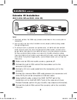
10
(B132-100A-MR and B132-100A-SR)
– Connect the built-in VGA
cable to the monitor’s VGA port. Connect a 3.5 mm audio cable
between the receiver unit and the monitor or external speakers.
(B132-200A-SR)
– The B132-200A-SR features two sets of VGA
and audio ports. Connect each set of ports to a set of monitors and
speakers using VGA video and 3.5 mm audio cables.
Installation
continued
15-04-118-9333BE.indd 14
4/8/2015 10:35:11 AM


