10
Features
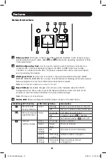
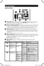
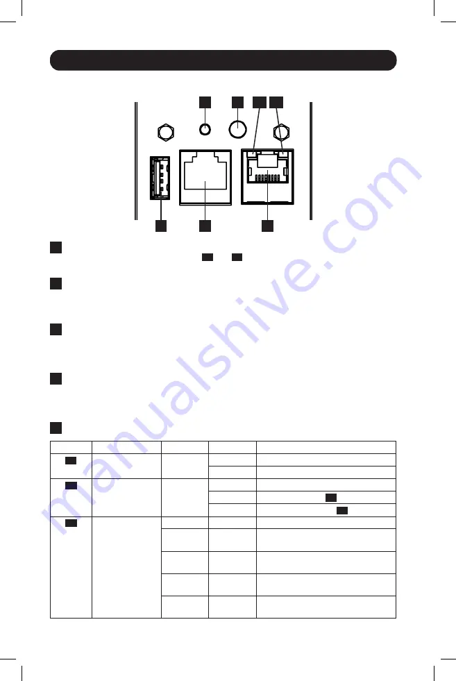
Network Interface
A
Ethernet Port:
RJ45 jack connects the PDU’s Network Interface to the network using a
standard Ethernet patch cable. LEDs
A1
and
A2
indicate the operating conditions (shown
in the table below).
B
RJ45 Configuration Port:
Use this port to provide a direct terminal connection to a
computer with a terminal emulation program. An RJ45 to DB9 cable (part number
73-1243) is included with the PDU. To request a replacement cable, visit www.tripplite.
com for ordering information.
C
USB Type-A Port:
Use this port to connect a Tripp Lite EnviroSense2 module (E2MT,
E2MTDO, E2MTDI, E2MTHDI) for a variety of environmental monitoring and control options.
See www.tripplite.com for more information about these modules.
Note:
Do not connect a keyboard or mouse to this port.
D
Reset Button:
Accessible through a small hole on the faceplate above the RJ45
Configuration Port. Press once to reset the Network Interface. Press and hold for 15
seconds to reset the Network Interface to factory default settings.
Note:
PDU loads will not be affected.
E
Status LED:
Shows the Network Interface status (shown in the table below).
Identifier LED Function
LED Color Status
Description
A1
Ethernet Link/
Activity Indicator
Green
Flashing
There is network activity on the port
Off
There is no network activity on the port
A2
Ethernet Network
Speed Indicator
Yellow
On steady
100 Mbps network speed
Off
10 Mbps speed if
A1
is flashing
Off
No network activity if
A1
is also off
E
Network
Interface Status
Green
On steady
Normal operation
Green
Single
flash
Power up indicator
Green/
Orange
Off
No power or card is initializing
Green/
Orange
Alternating
(~1/sec.)
Software update in progress
Green/
Orange
Alternating
(~2/sec.)
Restoring factory default
configuration
A
B
C
D
E
A1 A2
21-03-416-933666.indb 10
21-03-416-933666.indb 10
4/7/2021 12:21:32 PM
4/7/2021 12:21:32 PM


