background image


RESISTANCE MEASUREMENTS 


WARNING: 

To avoid electric shock, disconnect power to the 

unit under test and discharge all


capacitors before taking any 

resistance measurements. Remove the batteries and unplug 

the line cords. 


1. Set the function switch to the   Ω           position. 


2. Insert the black test lead banana plug into the negative 

COM jack. 


Insert the red test lead banana plug into the positive


jack. 


3. Press the MODE button to indicate “  ” on the display. 


4.  Touch  the  test  probe  tips  across 

the  circuit  or  part  under  test.  It  is 

best to disconnect one side of the 

part  under  test  so  the  rest  of  the 

circuit  will  not  interfere  with  the 

resistance reading. 


5. Read the resistance in the display. 


CONTINUITY CHECK 


WARNING: 

To avoid electric shock, never measure 

continuity on circuits or wires that have


voltage on them. 


1. Set the function switch to the Ω

 position. 


2. Insert the black lead banana plug into the negative COM 

jack. 


Insert the red test lead banana plug into the positive


jack. 


3. Press the MODE button to indicate“ " and “Ω” on the 

display 


www.

.com

[email protected]

1.800.561.8187

Содержание 614395002251

Страница 1: ...readings and a Low Z setting for eliminating false readings caused by ghost voltages Functions include AC DC voltage and current resistance continuity capacitance frequency duty cycle temperature and...

Страница 2: ...rly with regard to arc flash potential Use caution on live circuits Voltages above 30 V AC rms 42 V AC peak or 60 V DC pose a shock hazard Do not use if the meter or test leads if appear to be damaged...

Страница 3: ...www com information itm com 1 800 561 8187...

Страница 4: ...rcuits and Equipment in fixed installations such as 3 phase single phase lighting motors switchgear and distribution panels circuits in commercial Lighting circuits in commercial buildings buildings F...

Страница 5: ...DE button 5 Rotary function switch 6 10A input jack 7 A mA input jack 8 COM input jack 9 V Hz Diode Continuity Cap C F Input Jack 10 HOLD Backlight button 11 MAX MIN Average button 12 Flashlight PEAK...

Страница 6: ...Display Description www com information itm com 1 800 561 8187...

Страница 7: ...nce or Temperature MODE Button Used to select AC or DC Frequency or Duty Cycle Resistance Continuity or Diode Test and C or F REL button The RELATIVE function zeros out the reading on the display and...

Страница 8: ...CD display and the meter will display the running average The meter will update the reading when the average value changes 4 Press and hold the MAX MIN AVG button to end MAX MIN Average and return to...

Страница 9: ...4 Press and hold the PEAK button to exit PEAK and return to normal operation NOTE The meter does not Auto Range in the PEAK Mode The meter will display OL if the reading exceeds the range When this o...

Страница 10: ...r DC Symbol will appear on the LCD display 3 Insert the black test lead into the COM jack and the red test lead into the V input jack 4 Touch the test leads to the circuit under test If measuring DC v...

Страница 11: ...s to the circuit under test 5 Read the frequency or duty cycle on the LCD display Low Z AC DC Voltage WARNING Observe all safety precautions when working on live voltages Do not measure frequency or d...

Страница 12: ...he voltage on the LCD display AC DC Current Measurements 1 Insert the black test lead into the negative COM input jack 2 For current measurements up to 10A set the rotary function switch to the 10A po...

Страница 13: ...AC or DC symbol will appear on the LCD display 6 Remove power from the circuit under test then open up the circuit at the point where you wish to measure current 7 Touch the black test probe tip to t...

Страница 14: ...display 4 Touch the test probe tips across the circuit or part under test It is best to disconnect one side of the part under test so the rest of the circuit will not interfere with the resistance re...

Страница 15: ...e and V on the display 4 Touch the test probes to the diode under test Forward voltage will typically indicate 0 400 to 0 700V Reverse voltage will indicate OL Shorted devices will indicate near 0V an...

Страница 16: ...3 Press the MODE button to indicate F or C 4 Touch the Temperature Probe head to the part whose temperature you wish to measure Keep the probe touching the part under test until the reading stabilizes...

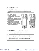
Страница 17: ...battery compartment 6 Install the battery fuse cover and tighten the screw s WARNING To avoid electric shock do not operate the meter until the battery fuse cover is securely fastened to the meter WAR...

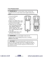
Страница 18: ...fast blow for the A mA ranges and 10A 1000V 10 x 38mm fast blow for the 10A range 6 Install the battery fuse cover and tighten the screw s WARNING To avoid electric shock do not operate meter until th...

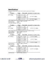
Страница 19: ...00V 1mV AC Voltage 60 00V 10mV 3 0 40 digits 600 0V 0 1V All AC voltage ranges are specified from 5 of range to 100 of range Input Protection 600V AC RMS or 600V DC Input Impedance approx 3k AC Respon...

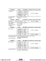
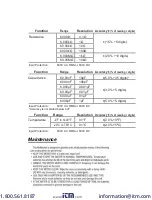
Страница 20: ...Function Range Resolution Accuracy of reading digits AC Current 600 0 A 0 1 A 6000 A 1 A 1 5 3 digits 60 00mA 10 A 600 0mA 0 1mA 10 00A 10mA 2 0 8 digits All AC current ranges are specified from 5 of...

Страница 21: ...ing digits Capacitance 60 00nF 10pF 5 0 35 digits 600 0nF 100pF 6 000 F 0 001 F 3 0 5 digits 60 00 F 0 01 F 600 0 F 0 1 F 6000 F 1 F 5 0 5 digits Input Protection 600V AC RMS or 600V DC Accuracy is no...

Страница 22: ...chase This warranty does not apply to any of our products which have been repaired or altered by unauthorized persons in any way or purchased from unauthorized distributors so as in our sole judgment...

Отзывы: