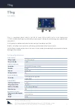


TTrig
//
Quick Guide
3
D04-05Aen201908 Quick Guide TTrig
TriOS Mess- und Datentechnik GmbH · Bürgermeister-Brötje-Str. 25 · D-26180 Rastede · Germany
Phone: +49 (0) 4402 69670 - 0 · Fax: +49 (0) 4402 69670 - 20 · [email protected] · www.trios.de
Commissioning
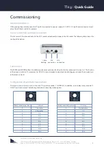
Electrical installation
After opening the protective cover, the TTrig is first connected to a power supply (12..24 VDC). A 2-pin Phoenix connector is locat-
ed on the left-hand side for this purpose.
Sensor connection and wiper connection
The sensor must then be connected to the M12 socket and optionally a wiper to the M8 socket. The following table shows the
configuration options.
Function test
The WIPER and SENSOR buttons should be operated manually one after the other for the subsequent function test. The function
of the wiper is visible by its movement. For OPUS it is recommended to download the data logger and check the completeness
of the measurements.
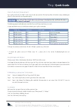
Configuration of automatic measurement
The measurement interval is set on site on the TTrig (rotary encoder "1. INTERVAL"). In addition, a start delay (rotary encoder "2.
DELAY") can be activated. The following table shows the configuration options.
Cable
bushing
M8
connection
M12
connection
Rotary encoder position
1.Interval
0
15 minutes
1
30 minutes
2
1 h
3
2 h
4
3 h
5
4 h
6
6 h
7
8 h
8
12 h
9
24 h
Rotary encoder position
2. Delay
0
No delay time
1
1 h
2
2 h
3
3 h
4
4 h
5
6 h
6
8 h
7
10 h
8
15 h
9
20 h


