Version 3.2
Page: 48
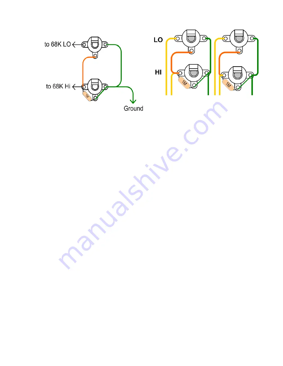
Optional Input to V1
–
Parts are not provided to do this but in some cases, it may be
desirable to eliminate noise for some Studio applications. This modification may help.
Acquire 2 - 3 terminal tag strips and install it at the base of V1 closest to the board. Use the
tube socket mounting bolts to hold the strips in place.
Connect the two 68K input resistors from two of the tags to the input (pin 7, pin 2) of V1.
Make the end that connects to the pins as short as possible. Repeat for pin 2.
Prepare some shielded cable (not provided) for connection and put some heat shrink over the
end to ensure there is no chance the shield will connect to ground or touch the tube pins.
Solder the shielded cable centre conductor to each 68K resistor on each tag.
On the input jack end, connect the 2 shields together, and connect them to the ground point
on the jacks. Do not connect the shields at both ends or you will induce hum.
Final checkout
When you finish assembling the amp, double-check the wiring and the components. Trace or
highlight the connections on a copy of the layout provided with the amp to ensure the amp is
wired correctly. Check everything at least once!
Measure the resistance from each part that has a ground connection to the chassis. Put your
probe on the parts lead. All readings should be less than 1 ohm, typically 0.5 ohms.
Make sure the Mains ground at the chassis is
very
tight.
Содержание Trinity Tweed Amp
Страница 2: ...Version 3 2 Page 2 ...
Страница 16: ......
Страница 20: ...Version 3 2 Page 20 Input Jack Theory from 18watt com ...
Страница 25: ...Version 3 2 Page 25 ...
Страница 49: ...Version 3 2 Page 49 ...
Страница 65: ...Version 3 2 Page 65 HEYBOER OT for TWEED 6L6GT CONVERSION ...
Страница 66: ...Version 3 2 Page 66 ...
Страница 75: ...Version 3 2 Page 75 ...
Страница 76: ...Version 3 2 Page 76 ...
Страница 77: ...Version 3 2 Page 77 Trinity Amps Schematics and Layouts ...


