Version 3.2
Page: 21
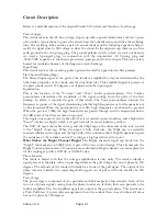
Circuit Description
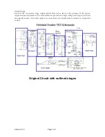
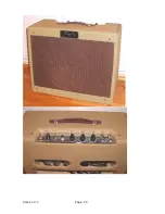
Below is a brief description of the original Fender 5E3 circuit and function of each stage.
Power Supply
This circuit takes in the AC line voltage, steps it up with a power transformer and uses 3 pairs
of secondary tap locations to power the circuit, heat the tube filaments, and drive the rectifying
tube. The rectifying tube contains a pair of vacuum diodes and the following capacitors help to
rectify the signal close to DC voltage to drive the circuit. In the original amp, there was no true
earth ground in the two prong plug. The ground polarity switch (which we took out because
we used a 3-pronged plug) in conjunction with the unpolarized AC 2-prong plug and
.05uF/500V capacitor to the chassis provided a quasi-ground for the chassis. This was a safety
hazard for musicians because of the dangerous static discharge.
Input Stage
This circuit receives the incoming guitar signal and sends the signal into the first preamp.
First/Second Preamp Stage
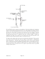
The filtered input signal at the grid of the triode is amplified by a factor determined by the
behavioral properties of the triode and the situational bias. This amplified signal is present at
the plate (anode) and is 180 degrees out of phase with the input signal.
Equalization
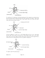
This is the location of the “Volume” and “Tone” knobs (potentiometers). The Volume
potentiometer determines the amplitude of the signal coming from the plate of the first
preamp. In effect, it controls the gain of that triode. The Tone potentiometer controls the
frequency response of the signal, determining whether high frequencies or low frequencies are
to be attenuated. When the poten
tiometer is at 0Ω, high frequencies are shunted to ground.
When the pot is at 1MΩ, the high frequencies are passed through and the frequencies below
the 3dB point of the filter are taken to ground.
This single tone control acts a treble roll off as it is rotated counter clockwise, and a high treble
"boost", similar to a bright switch, as it gets towards it's most clockwise position.
The .0047 uF cap is the treble cut cap, and the 500pf cap on the other end of the tone control
is the "bright" shunt cap. When the wiper is fully clockwise, the 500pf cap is essentially
connected between the wiper and the high side of the volume control. High frequencies bypass
the resistance of the volume control. It's acting as a high pass filter at this point.
What Makes the Bright Channel Bright?
The Bright channel's signal cap feeds into the
“bright” shunt capacitor (500pF) that is part of the
tone control design. This circumvents the
Bright Volume potentiometer. To obtain a more distinctive Bright channel, you can replace the
0.1uF coupling cap with a 0.047uF or 0.022uF value.
Phase Inverter
The triode is biased such that the voltage amplification is only unity. The result is ideally a
signal present at the plate with an equal magnitude as the grid voltage but out of phase by 180
degrees. The cathode of the triode will ideally be a clone of the grid signal. The output of the
phase inverter is ideally two equal magnitude signals out of phase with one another by 180
degrees.
Power Stage
The power stage is composed of two pentodes and their respective bias circuitry. Each of the
two out of-phase signals coming from the phase inverter are fed into their own pentode to be
further amplified. The two amplified signals are output at the pentode plates. This circuit uses
a Push-Pull Class A power tube arrangement where the current flows in each tube at all times
but out of phase by 180 degrees.
Содержание Trinity Tweed Amp
Страница 2: ...Version 3 2 Page 2 ...
Страница 16: ......
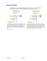
Страница 20: ...Version 3 2 Page 20 Input Jack Theory from 18watt com ...
Страница 25: ...Version 3 2 Page 25 ...
Страница 49: ...Version 3 2 Page 49 ...
Страница 65: ...Version 3 2 Page 65 HEYBOER OT for TWEED 6L6GT CONVERSION ...
Страница 66: ...Version 3 2 Page 66 ...
Страница 75: ...Version 3 2 Page 75 ...
Страница 76: ...Version 3 2 Page 76 ...
Страница 77: ...Version 3 2 Page 77 Trinity Amps Schematics and Layouts ...


