background image

HN440 USER’S GUIDE

I n s t a l l a t i o n           3 1

External connectors

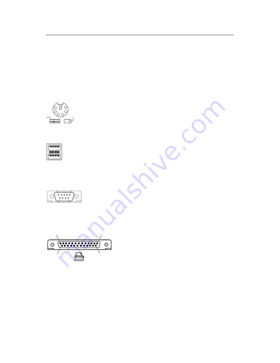
The HN440 ATX has all the necessary external connectors or
ports for your PC system. Note that the audio and
joystick/MIDI ports are present only on motherboard builds
with Audio.

PS/2 keyboard and mouse ports (items A and B on page
10).

6

4

2

1

3

5

Dual USB ports (item C on page 10).

Port 1

Port 0

1

4

1

4

Serial ports 1 and 2 (items D and E on page 10). 9-way D-
type connectors.

5

1

6

9

10101

Parallel (printer) port (item F on page 10). 25-way D-type
connector.

13

1

25

14

Audio line-out, line-in, microphone sockets (items G, H and
I on page 10). 3.5 mm stereo jack sockets. The line-out socket
is also suitable for 32 •  headphones. The microphone socket
provides phantom power to allow condenser-type
microphones to be used.

Joystick/MIDI port (item J on page 10). Requires an adapter
for use with MIDI devices.

Содержание HN440 ATX

Страница 1: ...TRIMOND HN440 ATX MOTHERBOARD USER S GUIDE www trimond com ...

Страница 2: ...mmitment on the part of Mitsubishi Electric No part of this manual may be reproduced or transmitted in any form or by any means electronic or mechanical including photocopying and recording for any purpose without the express written permission of the publishers Published by Mitsubishi Electric Motherboard Division 3500 Parkside Birmingham Business Park Birmingham England B37 7YS Copyright Mitsubi...

Страница 3: ...e processor can cause skin irritation and stain clothing Avoid prolonged or repeated contact with skin Wash thoroughly with soap and water after handling Avoid contact with eyes and inhalation of fumes Do not ingest Anti static precautions Warning Static electricity can cause permanent damage to electronic components You should be aware of this risk and take precautions against the discharge of st...

Страница 4: ...ities This product complies with the relevant clauses of the following European Directives and all subsequent amendments Low Voltage Directive 73 23 EEC EMC Directive 89 336 EEC CE Marking Directive 93 68 EEC Important This product when supplied complies with the CE Marking Directive and its legal requirements Use only parts tested and approved by Mitsubishi Electric s Motherboard Division Standar...

Страница 5: ...is no guarantee that interference will not occur in a particular installation If this equipment does cause harmful interference to radio or television reception which can be determined by turning the equipment off and on the user is encouraged to try to correct the interference by one or more of the following measures Reorient or relocate the receiving antenna Increase the separation between the e...

Страница 6: ...diagram 10 Motherboard block diagram 12 INSTALLATION 13 Installation steps 14 Jumper settings 15 System memory DIMMs 17 Processor 19 Expansion cards 23 Internal connectors 26 External connectors 31 Connecting to AC power 32 Replacing the motherboard battery 34 BIOS SETUP 35 USING THE SUPPORT CD 39 GLOSSARY 40 ...

Страница 7: ...l three package variations are supported SEPP Celeron SECC Pentium II and SECC2 Pentium II and Pentium III The motherboard is intended for use with a logic controlled soft switch Power Supply Unit PSU Such a PSU is needed for certain features of the motherboard such as Wake on LAN and power saving Suspend and Standby modes The HN440 has the following major build options Intel 440ZX or 440BX chipse...

Страница 8: ...dard fixing holes Intel AGPset Either Intel 440ZX or 440BX PCI AGP Controller build option plus PIIX4e Multifunction ISA Bridge PC100 Memory Support Either two 440ZX or three 440BX DIMM sockets supporting Intel PC100 66 compliant SDRAMs PC100 modules are required when using processors with a 100 MHz bus Either PC66 or PC100 modules may be used with 66 MHz bus processors See page 17 for more inform...

Страница 9: ...ng Suspend and Standby modes PCI ISA Expansion Slots One ISA slot one shared ISA PCI slot and three PCI slots AGP 2X Slot Supports either Accelerated Graphics Port 1X 66 MHz or 2X 133 MHz modes There is no on board video controller Wake on LAN Motherboard connector for input from network cards that support Wake on LAN technology System Management Desktop Management Interface DMI support in BIOS He...

Страница 10: ...HN440 USER S GUIDE 1 0 O v e r v i e w Motherboard layout diagram C D E F B A 22 4 J G H I 18 21 20 19 1 2 5 3 6 7 8 9 11 10 12 13 17 16 15 23 14 ...

Страница 11: ...12 Network card Wake on LAN connector 13 Audio disable jumper digital volume control PL24 14 AGP slot 15 ATAPI CD audio in 16 ATAPI audio line in 17 ATAPI telephony 18 Slot 1 processor socket 19 Chassis intrusion switch connector PL14 20 Processor fan connector PL15 21 Chassis fan connector PL11 22 DIMMs sockets build dependent 23 Hard switch power supply jumper Not supported A Keyboard B Mouse C ...

Страница 12: ... ICS9179 12 IC12 CLK BUFF ICS9179 12 IC12 CORE CHIPSET 443BX ZX IC13 DIMM Module SDRAM MM1 3 Telephony PL22 Parallel Port PL27 Floppy PL3 COM1 PL27 COM2 PL27 Super I O FDC37C677 IC25 AUDIO CODEC SOLO1 IC23 Line In 2 PL21 CD In PL20 Line In 1 PL26 Mic In PL26 ISA BUS Midi Joys PL26 Line Out PL26 Heceta II IC17 Mouse PL29 Keyboard PL29 ISA SLOT PL12 13 PCI ISA BRIDGE PIIX4E IC9 PCI SLOT PL16 19 Prim...

Страница 13: ...rd before carrying out any work inside the computer chassis Anti static precautions Computer motherboards processors memory modules and expansion cards are all vulnerable to static electricity To protect them against damage you should follow these precautions Unplug the computer from the AC power supply If possible always wear a grounded wrist strap Otherwise touch both your hands to a safely grou...

Страница 14: ... a t i o n Installation steps 1 Review jumper settings 2 Install memory modules 3 Install the processor 4 Install expansion cards 5 Connect internal ribbon cables and leads and the power supply 6 Connect external cables 7 Connect AC power ...

Страница 15: ...item 9 on page 10 This allows you to update the BIOS firmware when necessary 1 2 Disable BIOS updates 2 3 Enable BIOS updates BIOS updates disabled BIOS updates enabled Clear CMOS Memory PL1 item 7 on page 10 To clear configuration CMOS memory disconnect the AC power supply move the jumper to position 2 3 and wait for a few seconds then return the jumper to position 1 2 The jumper must be returned...

Страница 16: ...ed ratios in which case these jumper settings are ignored A B C D Processor speed ABCD Ratio Bus frequency 233 MHz o o o o o o o o 3 5 66 MHz 266 MHz o o o o o o o o 4 0 66 MHz 300 MHz o o o o o o o o 4 5 66 MHz 333 MHz o o o o o o o o 5 0 66 MHz 350 MHz o o o o o o o o 3 5 100 MHz 366 MHz o o o o o o o o 5 5 66 MHz 400 MHz o o o o o o o o 6 0 66 MHz 400 MHz o o o o o o o o 4 0 100 MHz 450 MHz o o...

Страница 17: ...put memory is not supported Error Checking Correcting ECC To use the 440BX chipset s ECC feature you must use 72 bit DIMM modules and make the proper settings within the BIOS Setup utility Choosing your memory modules The HN440 may fail to boot if non compliant memory modules are fitted The SDRAM DIMMs must be Intel PC100 or PC66 compatible see below 168 pin 64 bit wide 72 bit with parity ECC supp...

Страница 18: ...own The DIMM will only fit one way round because of the asymmetric notches along the edge Use the socket furthest from the processor marked MM1 first The DIMM is inserted vertically and held in place by the clips at each end Removing DIMMS Press down on the tabs at both ends of the socket at the same time This releases the DIMM and lifts it partly out of the socket ...

Страница 19: ... variations are supported SEPP Celeron SECC Pentium II and SECC2 Pentium II and Pentium III Examples of from the top SECC SECC2 and SEPP processor packages The motherboard uses a Universal Retention Mechanism URM that accepts all supported processors To install the processor you must Attach the heatsink to the processor package Insert the processor package into the Slot 1 connector ...

Страница 20: ...al applied to assure good heat transfer between the package and the heatsink Often there is a plastic film over the thermal interface material to protect it during shipping If so ensure that this protective cover is peeled off before attaching the heatsink Warning Thermal interface materials can cause skin irritation and stain clothing Avoid prolonged or repeated contact with skin Wash thoroughly ...

Страница 21: ...emove they are typically used for securing heatsinks in industrial quantities Some SECC heatsinks require an additional support bracket The bracket has two pieces a base that clips into the motherboard and a removable bar than grips the heatsink locking it onto the base The HN440 motherboard has two mounting holes for such a bracket located in front of the processor slot but the bracket itself is ...

Страница 22: ...ge into the URM The support arms guide the package so that it is positioned correctly over the Slot 1 processor connector 4 Push the processor package gently but firmly into the Slot 1 connector until it is fully inserted A SECC package has two catches on the top that engage with the URM support arms when the package is correctly inserted you will hear a click when this happens 5 If your SECC pack...

Страница 23: ...n or packaging that came with the card Installing an expansion card 1 Read carefully any documentation that came with your card If the card needs to be configured by the means of jumpers or switches check that it is correctly configured before proceeding 2 Ensure that the system is turned off and that the AC power cord is unplugged before working inside the computer s chassis 3 Remove the blanking...

Страница 24: ...on with a PnP aware operating system such as Windows 95 98 BIOS Setup includes an option called Plug and Play O S which should be set to Yes or No according to whether or not you have a PnP aware operating system If in doubt select No See the BIOS Setup chapter for details Legacy cards Most modern cards support Plug and Play For those that do not you may have to run the BIOS Setup utility and rese...

Страница 25: ...4 Click the Resources tab of the device s Properties dialog If your device does not have a Resources tab either you cannot change its resources or it isn t using any resource settings 5 Click the resource you want to change un check the Use Automatic Settings box then click Change Setting Tip In some cases you may see a Set Configuration Manually button on the Resources tab You may have to click t...

Страница 26: ...ms 4 and 5 on page 10 Typically the primary connector is used for the system s hard disk drives and the secondary or removable media drives such as CD ROM or tape Each connector can support two Enhanced IDE or ATAPI devices one Master and one Slave Refer to your drive s documentation or packaging to find out how to configure it as Master or Slave typically by repositioning jumpers on the drive IDE...

Страница 27: ...led speech modem expansion cards with voice mail capability CD Audio and Line in Pin Description 1 Left audio input 2 Signal ground 3 Signal ground 4 Right audio input Telephony Pin Description 1 Input from modem 2 Signal ground 3 Signal ground 4 Microphone output to modem Wake on LAN connector item 12 on page 10 for network cards that support Wake on LAN technology The Wake On LAN option in BIOS ...

Страница 28: ...I aware operating system such as Windows 98 Hard disk activity LED connector 13 16 4 pin connector for the lead to the chassis hard disk drive activity LED Read and write activity on the primary IDE interface cause the LED to light Power LED connector 18 20 3 pin connector for the lead to the chassis power LED A standard LED illuminates when the computer is powered on A two colour LED can also ind...

Страница 29: ...pin removed 13 Hard disk activity LED 14 Key pin removed 15 Ground 16 Hard disk activity LED 17 Key pin removed 18 Power LED 19 Key pin removed 20 Power LED 21 Key pin removed 22 Reset switch signal 23 Ground 24 Ground 25 Key pin removed 26 Ground 27 Internal speaker 28 Key pin removed 29 Message LED 30 Message LED Not Used Not Used Power LED Reset switch Message LED Speaker Hard Disk LED 1 30 Key...

Страница 30: ...tended to be used with a logic controlled soft switch Power Supply Unit PSU Use a PSU that supplies at least 30 mA on the 5 V standby rail For Wake on LAN to function the PSU must supply at least 720 mA Caution Ensure that the devices fitted in your system do not overload the 5 V standby rail or permanent damage to the motherboard may result ...

Страница 31: ...s item C on page 10 Port 1 Port 0 1 4 1 4 Serial ports 1 and 2 items D and E on page 10 9 way D type connectors 5 1 6 9 10101 Parallel printer port item F on page 10 25 way D type connector 13 1 25 14 Audio line out line in microphone sockets items G H and I on page 10 3 5 mm stereo jack sockets The line out socket is also suitable for 32 headphones The microphone socket provides phantom power to ...

Страница 32: ...omponent s power cords monitor to system unit if the PSU has a pass though AC port and system unit and any other peripherals to nearby grounded AC power outlets 4 Turn on the system unit first then the monitor then other peripherals Turning the system on and off The following instructions apply if you are using a logic controlled PSU and an operating system that supports the Advanced Configuration...

Страница 33: ...ect option which if enabled causes the system to turn itself on automatically when AC power is applied or when AC power is restored after any break or interruption Note If CMOS memory is cleared perhaps because the motherboard battery has become exhausted or has been removed the Wake On AC Connect option is ignored ...

Страница 34: ...ositive and negative terminals the battery may explode 1 Turn off the computer and unplug all power cords 2 Using a non conductive tool release the latch that holds the battery in place The battery will pop up allowing you to lift it out of the holder 3 Taking care not to touch the top or bottom surface of the new battery pick up the replacement with the positive terminal upwards and press the bat...

Страница 35: ...pervisor password you are prompted for it before BIOS Setup starts Control keys Use the keys listed in the legend bar at the bottom of the BIOS Setup screen to make your selections or exit the current menu see table on next page Sub menus are marked by a triangular pointer To display a sub menu use the arrow keys to move the cursor to the sub menu you want then press Enter Changeable fields are en...

Страница 36: ...the next or previous page of the current menu F9 Restore the default settings for the fields on the current menu F10 Save the changes you ve made and exit from BIOS Setup Getting help in BIOS Setup You can at any time get general help about the control keys by pressing the F1 key The help window on the right hand side of each menu displays help text for the currently selected field It changes as y...

Страница 37: ... Perhaps the most important item on this menu is that which allows you to declare whether your operating system supports Plug and Play PnP The PCI Configuration sub menu allows you to reserve interrupts and upper memory block UMB regions for legacy non PnP expansion cards You can also fine tune the configuration of your system s PCI devices and the serial and parallel ports Security menu Use this ...

Страница 38: ...OS settings Usually you would save and exit The Boot Menu If you press Esc during the Power On Self Test POST a menu similar to the following appears Boot Menu 1 Diskette Drive 2 Removable Devices 3 Hard Disk Drive 4 ATAPI CD ROM Drive 5 Network Boot Enter Setup This menu can be used to select the drive or device from which to boot your system for example a bootable CD ROM without having to enter ...

Страница 39: ...porary and some historical motherboards from Trimond The information is provided in a set of HTML files that can be viewed with most modern web browsers Microsoft Internet Explorer 4 or later is recommended To use the CD simply insert it in the computer s CD ROM drive and use your browser to open the index html file in the root of the CD ...

Страница 40: ...trol Windows 98 is an example of an ACPI aware operating system ATAPI Advanced Technology Attachment Packet Interface An interface for removable media drives ATAPI is part of the Enhanced Integrated Drive Electronics EIDE interface also known as ATA 2 ATX ATX is an industry wide open specification for motherboard layout and placement ATX improves motherboard design by allowing space for more full ...

Страница 41: ...llel signalling methods EPP is for non printer peripherals ECP is for printers and scanners EPP ECP are part of IEEE Standard 1284 ISA Industry Standard Architecture ISA is a standard bus architecture associated with the original IBM AT motherboard Although superseded technologically many expansion cards continue to use it logic controlled Power Supply Unit PSU Also known as a soft switch PSU A PS...

Страница 42: ...s to insert and remove SDRAM Synchronous Dynamic Random Access Memory A generic name for various kinds of memory that are synchronised with the clock speed for which the processor is optimised This tends to increase the number of instructions that the processor can perform in a given time The speed of SDRAM is rated in MHz rather than in nanoseconds SECC Single Edge Contact Cartridge Packaging use...

Страница 43: ... be attached without having to turn off the computer USB supports a data speed of 12 megabits per second and can also supply DC power to certain devices Wake On LAN Provides the capability to remotely power on a networked computer simply by sending it a Wake On LAN packet Wake on LAN support must be provided by the motherboard BIOS network adapter operating system and client software plus a logic ...

Отзывы: