

Page 8 of 14
Part Number 8519184-0000 Rev: B
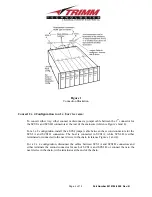
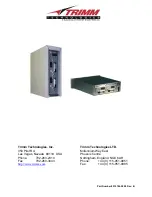
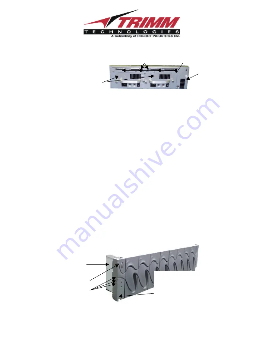
Figure 4
Rear View
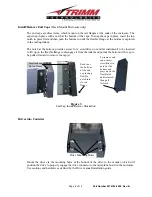
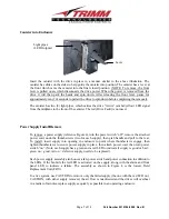
Fan (Auxiliary Blower) Install/Remove
To remove the fan assembly (Reference Figure 4), undo the thumbscrew and pull the assembly to
the rear, by pulling on the thumbscrew. To install, push assembly into place and tighten the
thumbscrew. (Note, the fan assembly has a bi-color LED to indicate whether or not the fan is
okay; green = okay; red = fan is defective and needs replacement).
Electronic Circuit Boards
Within the enclosure, there are three (3) (four if optional Saf-Te is installed) circuit boards:
1.
On the left front ear (end cap), there is an enclosure status (front display) board, which has
three (3) bi-color LEDs which indicate the status of the power supplies (top LED), enclosure
fans (middle LED) and temperature (bottom LED) within the enclosure. The temperature
LED is red if the enclosure temperature exceeds 45
°
C. Green indicates okay operation, while
red indicates a problem with the associated function. This board contains the audible alarm
reset switch. When an alarm is triggered, it can be deactivated by pressing the reset switch.
This board is a FRU.
For access to the Display Board , in the Rack Mount, remove the left End Cap. In the Tower
enclosure, remove the stabilizer foot (2 philips screws), then remove the cover (3 philips
screws at rear and then pull cover to the rear), next, remove the front bezel (4 Torx screws,
requires a T20 Torx bit).
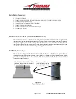
Host Connections
Base Address Switches
Fan
Power Supply
Front Display
Board (mounted
on left ear)
Alarm Reset
Switch
LEDs
To remove the end cap, insert a
screwdriver in the notch at the
bottom of the cover to release the
tab, then pull the cap forward
Содержание UR8J2-4 Series
Страница 2: ...Part Number 8519184 0000 Rev B...


