TriangleTube Instinct FSB Скачать руководство пользователя страница 5

5

Instinct FSB (Floor Standing Boiler) 

HMI (Human Machine Interface) Removal

WARNING

!

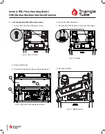
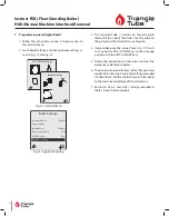
Be careful when using the flat blade screwdriver.  Do not 

cause damage to the surface of the Wi-Fi Module 21.

4.  Remove the Wi-Fi Module 21

1.  Locate the Wi-Fi Module 21.  Using a flat head 

screwdriver, carefully ease-out the Wi-Fi Module 21 

from either the top or bottom of the module.

Reset

Power

Reset

Fig. 12:  Wi-Fi Module 21 Removal

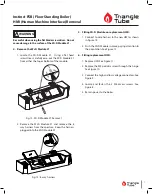
2.  Remove the Wi-Fi Module 21 and remove the 8 

way harness from the aperture.  Keep the harness 

plugged into the Wi-Fi Module 21.

Reset

Power

Fig. 13:  8-way harness

5.  Fitting Wi-Fi Module on replacement HMI.

1.  Connect to wire harness to the new HMI as shown 

in Figure 13.

2.  Push the Wi-Fi Module in place, paying attention to 

the orientation. See Figure 12.

6.  Fitting replacement HMI.

1.  Replace HMI. See Figure 11.

2.  Replace the M5 pozidriv screw through the hinge. 

See Figure 10.

3.  Connect the high and low voltage connectors. See 

Figure 9.

4.  Locate and fasten the 2 M6 access screws. See 

Figure 8.

5.  Return power to the boiler.

Содержание Instinct FSB

Страница 1: ...ool before pro ceeding to avoid possible electrical shock and scald hazard Failure to do so can cause severe personal injury or death WARNING Failure to follow instructions below can result in severe...

Страница 2: ...dule s Use Table 1 to record the existing settings Do not revise any settings when recording settings 1 To access the Installer screen touching simultane ously the up and down soft keys for 3 seconds...

Страница 3: ...Enabled Switch 186 F 140 F 6 F 46 F Fig 7 DHW Settings 9 Press the DOWN button to highlight the Boiler Settings icon if present icon then press the OK button 10 Press the UP and DOWN buttons to scroll...

Страница 4: ...screws 1 Locate and undo the 2 M6 access screws Fig 8 Access Screws 2 Raise the HMI Pod 3 Disconnect the high and low voltage connectors Fig 9 High and Low Voltage Connectors 4 Rotate the HMI Pod down...

Страница 5: ...2 Remove the Wi Fi Module 21 and remove the 8 way harness from the aperture Keep the harness plugged into the Wi Fi Module 21 Reset Power Fig 13 8 way harness 5 Fitting Wi Fi Module on replacement HMI...

Страница 6: ...pliance Setting 3 The required code is written on the data plate located at the side of the boiler Use the code for the gas type either Natural Gas or Propane 4 Increase decrease the value from 0 to 9...

Страница 7: ...reeze Protection Enabled Frost Protection Setpoint 22 F 30 C 22 F 30 C 50 F 10 C Parallel Shift Value 0 F 0 C 0 F 0 C 144 F 80 C CH Call Blocking 2 Minutes 0 Minutes 30 Minutes DOMESTIC SETTING SOLO F...

Страница 8: ...dbus Address 0 BCST 0 BCST 247 Flex Relay 1 CH CH1 Flex Relay 2 DHW DHW Flex Relay 3 P3 CH1 CH2 DHW Flex Relay 4 ERR ERROR Flex Relay 5 Flame FLAME Flex Relay 6 P4 CH2 Error Relay On Lockout Blocking...

Отзывы: