16
TRI TOOL INC.
92-1783 Orig. 161006
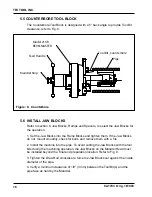
5.5 COUNTeRBORe TOOL BLOCk
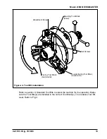
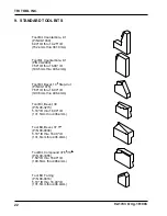
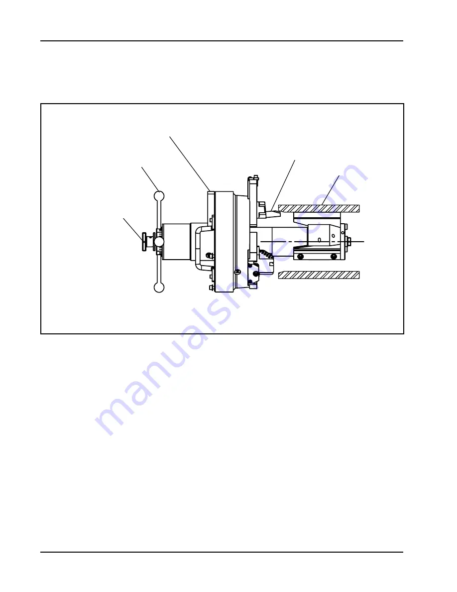
The Counterbore Tool Block is designed with a 5° back angle to provide Tool Bit
clearance, refer to Fig. 8.
5.6 INsTALL JAW BLOCks
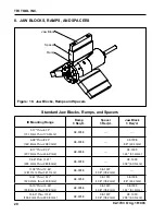
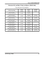
Refer to section 8, Jaw Blocks, Ramps and Spacers, to select the Jaw Blocks for
the operation.
1. Set the Jaw Blocks into the Ramp Blocks and tighten them. If the Jaw Blocks
do not mount smoothly, check for burrs and remove them with a file.
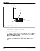
2. Install the machine into the pipe. To avoid cutting the Jaw Blocks with the tool
bits during the machining operation, the Jaw Blocks on the Mandrel Head must
be installed beyond the final end preparation location. Refer to Fig. 9.
3. Tighten the Draw Rod clockwise to force the Jaw Blocks out against the inside
diameter of the pipe.
4. Verify a minimum clearance of 1/8” (3 mm) between the Tool Bit(s) and the
pipe face as held by the Mandrel.
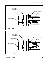
figure: 8. Counterbore
Pipe
Tool Bit, Counterbore
Model 216B
BEVELMASTER
Feed Handle
Mandrel Stop
Tool Bit Counterbore
Содержание BEVELMASTER 216B
Страница 1: ...92 1783 Orig 161006 Model 216B BEVELMASTER ...
Страница 31: ...29 Model 216B BEVELMASTER 92 1783 Orig 161006 Page intentionally left blank ...
Страница 53: ......

