background image

5

Model 201BA BEVELMASTER

TM

92-0631 : Orig. 960119

Disconnect power supply during setup and maintenance.  Use all ‘Stop’ or Shut off’
features available when changing or adjusting tool bits, maintaining the tool, or when
the tool is not in use.

Remove adjusting keys and wrenches before applying power to the equipment.
Develop a habit of checking the tool before turning it on to make sure that all keys
and wrenches have been removed.

Do not force tools.  Tools and tool bits function better and safer when used at the
feed and speed rate for which they were designed.

Do not reach into rotating equipment.  Do not reach into the rotating head stock to
clear chips, to make adjustments, or to check surface finish.  A machine designed to
cut steel will not stop for a hand or an arm.

Handle chips with care.  Chips have very sharp edges and are hot.  Do not try to pull
chips apart with our hands; they are very tough.

Avoid unintentional starts.  Do not carry or handle tools with your hand on the oper-
ating switches or levers.  Do not lay the tool down in a manner that will start the
drive.  Do not allow the tool to flip around or move when adjusting or changing tool
bits.

Store idle tools properly.  Disconnect tools from the power source and store in a safe
place.  Remove tool bits for safe handling of the tool.

Содержание 01-1320

Страница 1: ...t Cover SAFETY PRECAUTIONS 3 GENERAL DESCRIPTION 6 SPECIFICATIONS 7 MAINTENANCE 9 OPERATION 12 CUTTING SPEEDS 19 TOOL BITS 21 FIXED SADDLES 23 TROUBLE SHOOTING 25 ACCESSORIES 27 ILLUSTRATED PARTS BREAKDOWN 28 TOOL BIT RESHARPENING POLICY Inside Back Cover WARRANTY INFORMATION Inside Back Cover ...

Страница 2: ...Copyright 2005 Proprietary property of TRI TOOL Inc No reproduction use or duplication of the information shown hereon is permitted without the express written consent of TRI TOOL Inc ...

Страница 3: ...s Do not operate cutting tools without eye protection Dress properly Do not wear loose clothing or jewelry They can be caught in rotat ing and moving parts Avoid slippery floors or wear nonskid footwear If you have long hair wear protective hair covering to contain it WORK AREA Keep the work area clean Cluttered work areas and benches invite injuries Consider the work area environment Keep the are...

Страница 4: ...ut of all cutting fluids and water Hydraulic drives Observe proper procedures for electrically driven power sources Avoid damage to hydraulic lines Keep quick disconnects clean Grit contamination causes malfunctions Air tools Check the exhaust muffler Broken or damaged mufflers can restrict air flow or cause excessive noise Use air motors only with a filtered lubricated and regulated air supply Di...

Страница 5: ... were designed Do not reach into rotating equipment Do not reach into the rotating head stock to clear chips to make adjustments or to check surface finish A machine designed to cut steel will not stop for a hand or an arm Handle chips with care Chips have very sharp edges and are hot Do not try to pull chips apart with our hands they are very tough Avoid unintentional starts Do not carry or handl...

Страница 6: ...ng having an outside diameter of 250 to 2 000 6 4 mm to 50 8 mm The Clamping Saddle Fixed Saddle provides an accurate self centering and alignment to the pipe or tubing to be machined The Adjustable Saddle Assembly features an adjustable Saddle for adjusting the centerline of a pipe or tubing working with the Clamping Saddle There are two sizes of Adjustable Saddles The Small Adjustable Saddle cov...

Страница 7: ...7 Model 201BA BEVELMASTERTM 92 0631 Orig 960119 SPECIFICATIONS Model 201BA with an Air Motor Weight 15 lbs 6 8 kg Power Requirements 32 cfm at 90 psi 15 L s at 621 kPa Envelope Model 201BA BEVELMASTERTM ...

Страница 8: ...ed Contact TRI TOOL Inc for heavier wall procedures MATERIAL CUTTING CAPABILITIES Mild steels chrome steels Rc 35 maximum stainless steel copper nickel and aluminum without limitations except size and wall thickness as specified in previous paragraph Inconel and some other high temperature alloys may require special procedures as a function of wall thickness and type of end preparation Contact the...

Страница 9: ...r Air supply for the Model 201BA with an Air Motor requires an adequate filter regulator lubricator FRL to be used A maximum of 90 psi 621 kPa line pressure is recommended Clean Up The motor warranty is void if damage occurs from contaminated air or lack of lubrication If the Model 201BA is operated in the vertical position cutting head up it should be turned upside down and the chips and or other...

Страница 10: ...ower unit voids warranty except when performed by a TRI TOOL Inc designated repair technician A letter of designation is required AIR MOTOR LUBRICATION No direct maintenance is normally required on the Air Motor However the air supply must flow through a filter regulator lubricator FRL unit or separate units before arriving at the Air Motor The FRL unit must be maintained as required frequency dep...

Страница 11: ...reezing of the Rotor Vanes LUBRICANT RECOMMENDATIONS The Air Motor requires a Class 2 lubricant viscosity of 100 to 200 SSU at 100O F 38O C minimum aniline point of 200O F 93O C TRI TOOL Inc Air Tool Lubricant P N 68 0022 AMOCO American Industrial Oil No 32 Atlantic Richfield Duro Oil S 150 Chevron A W Machine Oil 32 Exxon Nuto H32 Shell Tellus Oil 32 The bearings in the Air Motor are sealed and d...

Страница 12: ...he Hex Head Screw on the front of the Model 201BA Turn the Adjustment Feed Screw to raise or lower the Adjustable Saddle Select the line on the side of the Adjustable Saddle and adjust the height so that the desired line is even with the seat of the Main Housing One side of the Saddle is marked with pipe sizes and the other is marked with tube sizes Tighten the Hex Head Screw on the front of the M...

Страница 13: ...dle The Clamping Saddle Nut is turned lowering the Clamping Saddle down onto the pipe or tube Pipe Position when seated between the Saddles Tool Bit to pipe clearance Continue this operation until the pipe or tube is clamped securely between the Adjustable Saddle and the Clamping saddle Verify a clearance of 1 8 3 2 mm minimum between the Tool Bit and the pipe or tube face ...

Страница 14: ...cutting edge of the Tool Bit s must be located on the radial centerline Make sure that there are not any tooll bits installed backwards Make sure that there is a clearance between the Tool Bit s and the Saddles Tool Bit Positioning Tighten the Set Screws to secure the Tool Bit s to the Cutting Head Attach the proper air supply line to the Model 201BA Check that the filter regulator lubricator FRL ...

Страница 15: ...l the end of the pipe is completely machined Discontinue feed and allow the Head to rotate 1 to 3 revolutions to improve finish of the prep surface Release the Air Motor Trigger to stop the Head rotation Rotate the Feed Handle counterclockwise to separate the Tool Bit s from the pipe Rotate the Feed Handle counterclockwise until the Head to Saddle relationship is the same as described in The Clamp...

Страница 16: ...d Saddle Remove the 4 four Cap Screws from the bottom of the Retaining Bracket Assy and 2 two Cap Screws from the front Removal of the Adjustable Saddle from the Model 201BA Remove the Retaining Bracket Assy from the front of the Model 201BA Insert the Fixed Saddle Adapter into the front of the Model 201BA Attach the Fixed Saddle Adapter by using 4 four Cap Screws from the bottom and 2 two Cap Scr...

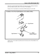
Страница 17: ...e machined Refer to the Fixed Saddle selection chart in the section Fixed Saddles Gently set the Fixed Saddle into the Model 201BA locating it over the Slot Installation of the Fixed Saddle Adaptor into the Model 201BA Tighten the 2 two Captive Cap Screws which will secure the Fixed Saddle to the Model 201BA ...

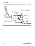
Страница 18: ...18 TRI TOOL INC 92 0631 Orig 960119 Installing the fixed Saddle into the Model 201BA ...

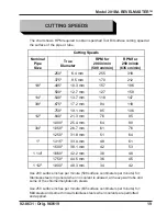
Страница 19: ...per minute 635 surface centimeters per minute for Mild steels and some thin wall stainless steels when coolants are permitted and applied Nominal Pipe Size RPM for 200 in min 508 cm min RPM for 250 in min 635 cm min 250 6 4 mm 255 318 375 9 5 mm 170 212 1 8 405 10 3 mm 157 196 500 12 7 mm 127 159 1 4 540 13 7 mm 118 147 3 8 675 17 2 mm 94 118 750 19 1 mm 85 106 1 2 840 21 3 mm 76 95 1 000 25 4 mm ...

Страница 20: ... revolution there after to establish a continuous chip cut If the feed is too light only light stringer chips will be removed If the feed is too heavy the drive will start to overload and the chip will start to have a rough or torn appearance Stainless steel which work hardens must be worked with a heavy enough feed to stay under the work hardened surface 003 to 006 08 mm to 15 mm feed Never allow...

Страница 21: ... 4040 630 thru 880 ID Low Carbon 99 4034 99 4000 16 0 mm thru 22 4 mm ID Stainless 99 4038 99 4040 800 thru 1 050 ID Low Carbon 99 4035 99 4000 20 3 mm thru 26 7 mm ID Stainless 99 4039 99 4040 900 thru 1 150 ID Low Carbon 99 4132 99 4000 22 9 mm thru 29 2 mm ID Stainless 99 4133 99 4040 1 150 thru 1 400 ID Low Carbon 99 0944 99 4000 29 2 mm thru 35 6 mm ID Stainless 99 3574 99 4040 Cobalt High He...

Страница 22: ...O BEVELING TOOL BITS For Beveling only with the 1 45 or 2 00 dia Cutting Head 355 9 02 mm maximum wall Range Pipe or Tube Material 37 5 O Beveling Tool Bit P N Facing Tool Bit P N 125 thru 928 ID Low Carbon 99 4032 99 4000 3 2 mm thru 23 6 mm ID Stainless 99 4036 99 4040 664 thru 1 470 ID Low Carbon 99 4034 99 4000 16 8 mm thru 37 3 mm ID Stainless 99 4038 99 4040 900 thru 1 550 ID Low Carbon 99 4...

Страница 23: ...1 500 12 70 mm 26 1102 1 4 540 13 72 mm 26 1103 625 15 88 mm 26 1272 3 8 675 17 15 mm 26 1104 750 19 05 mm 26 1105 1 2 840 21 34 mm 26 1106 875 22 23 mm 26 1175 1 000 25 40 mm 26 1107 3 4 1 050 26 67 mm 26 1108 1 125 28 58 mm 26 1273 1 250 31 75 mm 26 1109 FIXED SADDLES True Outside Diameter Contact TRI TOOL Inc for sizes not listed Table Continues on next page ...

Страница 24: ... 26 1110 1 375 34 93 mm 26 1274 1 500 38 10 mm 26 1111 1 625 41 28 mm 26 1275 1 1 4 1 660 42 16 mm 26 1112 1 750 44 45 mm 26 1113 1 875 47 63 mm 26 1209 1 1 2 1 900 48 26 mm 26 1114 2 00 50 80 mm 26 1115 FIXED SADDLES True Outside Diameter Contact TRI TOOL Inc for sizes not listed ...

Страница 25: ...fast Cutting fluid is required A dull Tool Bit is causing surface hardening conditions Stainless pipe or tubing There is scale or other foreign matter on the pipe or tube which is dulling the tool bit at the start of the cut The tool bit is incorrect for the material being cut Problem The surface finish is rough Probable causes The tool bit is dull chipped etc Metal build up on the cutting edge of...

Страница 26: ...he hydraulic supply pressure is too low The hydraulic filter is plugged The hydraulic line size is insufficient The hydraulic line is too long Problem The tool bit will not reach the work Probable causes Incorrect tool blocks are installed for the size of the pipe or tube being worked on Incorrect tool bit is installed Problem The hydraulic motor will not start Probable causes The hydraulic power ...

Страница 27: ...2 Tool Bits Refer to Tool Bit Section 3 Headstock Kits 1 45 dia Head Kit P N 03 0037 2 00 dia Head Kit P N 03 0038 4 Adjustable Saddle Kits Small Adjustable Saddle Kit P N 05 0241 Diameter range 250 to 600 Diameter range 6 4 mm to 15 2 mm Large Adjustable Saddle Kit P N 05 0242 Diameter range 600 to 2 000 Diameter range 15 2 mm to 50 8 mm Full Range Adjustable Saddle Kit P N 05 0243 Diameter range...

Страница 28: ...0631 Orig 960119 MODEL 201BA BEVELMASTERTM SUB ASSEMBLY ILLUSTRATED PARTS BREAKDOWN 1 10 2 3 4 5 7 6 9 11 12 13 15 14 19 18 17 16 20 21 22 23 24 25 26 27 29 30 31 32 33 34 35 36 37 38 39 43 44 40 41 42 45 5 18 30 12 20 27 ...

Страница 29: ...NG KEYLESS 1 17 32 0140 PIN DOWEL 1 18 33 0029 SCREW CAP 10 24 X 5 8 8 19 33 0040 SCREW CAP 1 4 20 X 3 4 4 20 33 0056 SCREW CAP 5 16 18 X 1 2 21 33 0058 SCREW CAP 5 16 18 X 1 1 2 1 22 33 2017 SCREW CAP 10 32 X 5 8 1 23 33 0273 SCREW CAP 10 32 X 3 8 2 24 33 0459 SCREW SET 10 40 X 5 16 CUP PT 1 25 33 0928 SCREW SET 1 4 20 X 3 8 HDOG 2 26 33 1654 SCREW FEED LH 1 27 34 0192 WASHER THRUST 4 29 34 0245 ...

Страница 30: ...NG GREASE 1 45 54 0304 PLUG PRESSURE 1 36 0001 WRENCH L 1 16 HEX 1 36 0008 WRENCH L 3 16 HEX 1 36 0010 WRENCH L 1 4 HEX 1 36 0011 WRENCH L 5 16 HEX 1 36 0018 WRENCH T 1 8 HEX 1 36 0020 WRENCH T 5 32 HEX 1 36 0075 WRENCH COMBINATION 1 2 1 86 0170 CASE CUSTOM CARRYING 1 Parts List Model 201BA BEVELMASTERTM Continued Item Part No No Description Qty NOT SHOWN ...

Страница 31: ...Parts List Motor Assy Air P N 57 0156 Item Part No No Description Qty 1 28 0219 SEAL GREASE 1 2 34 0246 WASHER FLAT 1 3 39 0582 GEAR ASSY PINION 1 4 53 0045 VALVE AIR FLOW CONTROL 1 5 54 0149 COUPLING MALE QD 1 6 54 0201 CAP YELLOW 1 7 57 0077 MOTOR AIR 1 1 2 3 4 5 6 7 ...

Страница 32: ...ad Kit 2 00 dia P N 03 0038 Item Part No No Description Qty 1 21 0325 HEAD 1 45 DIA 1 2 33 0039 SCREW CAP 1 4 20 X 5 8 2 3 33 0499 SCREW SET 1 4 20 X 1 4 CUP PT 2 4 33 0501 SCREW SET 1 4 20 X 3 8 CUP PT 2 1 21 0326 HEAD 2 00 DIA 1 2 33 0039 SCREW CAP 1 4 20 X 5 8 2 3 33 0499 SCREW SET 1 4 20 X 1 4 CUP PT 2 4 33 0503 SCREW SET 1 4 20 X 1 2 CUP PT 4 1 2 3 4 ...

Страница 33: ...33 Model 201BA BEVELMASTERTM 92 0631 Orig 960119 BLANK PAGE ...

Страница 34: ...34 TRI TOOL INC 92 0631 Orig 960119 ADJUSTABLE SADDLE KIT 1 2 3 4 5 7 6 6 ...

Страница 35: ...4 33 1654 SCREW FEED LH 1 5 33 1951 SCREW HEX HD CAP 5 16 18 X 5 8 1 6 34 0192 WASHER THRUST 2 7 47 0972 BRACKET RETAINING 1 1 19 0690 HOUSING MAIN REF 2 26 1376 SADDLE ADJUSTABLE LARGE 1 3 33 0028 SCREW CAP 10 24 X 1 2 6 4 33 1654 SCREW FEED LH 1 5 33 1951 SCREW HEX HD CAP 5 16 18 X 5 8 1 6 34 0192 WASHER THRUST 2 7 47 0972 BRACKET RETAINING 1 1 19 0690 HOUSING MAIN REF 2 26 1376 SADDLE ADJUSTABL...

Страница 36: ...t Fixed Saddle P N 05 0244 Item Part No No Description Qty 1 2 3 4 5 6 4 1 19 0690 HOUSING MAIN REF 2 26 XXXX SADDLE FIXED REFER TO FIXED SADDLE SECTION REF 3 27 0490 ADAPTER SADDLE FIXED 1 4 33 0028 SCREW CAP 10 24 X 1 2 6 5 33 0056 SCREW CAP 5 16 18 X 1 2 6 34 0233 WASHER THRUST 2 ...

Отзывы: