

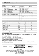

SERVICING
FAULT
CAUSE
ACTION
Machine bounces in use
Air pressure to high.
Ensure that the air pressure is set at 90psi. (6.3bar).
If the air pressure cannot be controlled, close off the SF11
on/off valve slightly until the machine runs smoothly.
Machine performance slow
Worn Cutter Heads
Replace Cutter Heads (Cutter Head life is approximately
100hrs use)
Machine drags on deck or floor
Insufficient air supply
Ensure that the compressor can supply at least 100cfm (free
air) at 90psi. The SF11 Deck Scaler requires 70cfm
Hose bore to small
Ensure that the hose bore is 3/4” (19mm).
Hose run to long
Each 50 ft. (15 metres) of airline used, will drop the pressure
by approximately 3 psi.
Worn Pistons and/or cylinders.
Replace piston and cylinders
If the problem has not been cured by any of the above actions, contact your local dealership or agent for assistance.
Trouble Shooting
main handle (14). Insert the bolt (9) and fit a
washer (8a) and nut (8). Fit the handle-locking
pin (11). Select a 13mm A/F spanner to suit (8)
and a 6mm A/F Allen key to suit caphead
screw (9). Tighten both nut and bolts (8) & (9)
ensuring that the pin hole is central and the
locking pin can be removed and inserted easily.
Machine storage
Short period storage: up to 3months.
Clean the outside of the machine and inspect
the cutter heads for wear, replace any worn
parts as required. Insert a liberal quantity of air
tool oil through the air inlet and run briefly to
ensure that internal components are coated
with oil. Cover the machine to protect it: Store
the machine in a dry place.
Long period storage: over 3months
Clean outside of machine, inspect the cutter
heads for wear; replace any worn parts as
required. Remove any build up of material from
the cutter head area. Insert a liberal quantity of
air tool oil through the air inlet and run briefly to
ensure that internal components are coated
with oil. Lubricate the exposed part of the
piston and cylinder. (See recommended
lubricants) Cover the machine to protect it:
Store the machine in a dry place.
After a further 3 months have elapsed, insert oil
into the air inlet as previously described.
When next used, continue as per “Starting work
section”.
Machinery Directive
Information
This tool has been designed and produced in
accordance with the following directives:
2006/42/EC Machinery Directive
and applicable harmonised standard:
EN ISO 1 1148-4:2010
If your company has any problem with our
products or would like to discuss the possibility
of an improvement being made to them, then
please do not hesitate to contact us. Your
comments are both important and appreciated.
The company operates a policy of continuous
product development and refinement and
therefore reserves the right to change technical
specifications and product designs without
giving prior notice.
All rights reserved. Any unauthorised use or
copying of the contents or part thereof is
prohibited. This applies to trademarks, model
denominations, part numbers and drawings.
Use only genuine Trelawny spares. The use
of non-Trelawny spare parts invalidates the
warranty.
Assembly of Scaling Head
Removal all traces of oil from screwed cap and
cylinder block threads. Select a cutter head/
piston/cylinder/brush seal assembly and apply
a few drops of air tool oil to the top of the piston
and fit into the body (30), repeat with the other
assemblies. Fit spring (26) into a screwed cap
(25) and fit spring cap (27) into screwed cap, as
shown in the service layout. Apply a small bead
of Loctite 243 (Threadloc) or its equivalent to
the first two threads of the spring cap and
screw down by hand, fully tighten the screwed
cap using a suitable spanner, to a torque of
81.5 Nm (60 lb/ ft).
Sub-frame to Scaling Head
Align mounting holes on sub-frame (22) with
anti-vibration pad (21) studs and fit as shown in
service layout. Fit washer (20) and locknut (19)
to both studs and fasten both nuts down to a
torque of 40lb ft
Wheel to Sub-frame
Slide wheel (23) onto sub-frame axle, fit washer
(20) and insert a new split pin (24) into the hole.
Separate legs on split pin and bend round with
pliers or otherwise. Repeat on the other wheel.
Handle to Sub-frame
Fit washer (17) to bolt (16) and align all holes
though chassis and anti-vibration mountings
(18) guide the bolt through until it appears at
the other end. Fit washer (17) to threaded end
of bolt and fit nut (15). To ensure that the sub-
frame does not twist or buckle through over
tightening of the nyloc nut (15), tighten so that
not more than 3/8” (10mm) of thread it
protruding from the nyloc nut (15). Select a
13mm A/F spanner to suit (8) and a 6mm A/F
Allen key to suit caphead screw (9). Slacken off
both bolts (9) and nuts (8) align the lifting plate
(10) to the lifting block (12) and insert the
locking pin (11). Ensure that the pin hole is
central and the locking pin can be removed and
inserted easily, adjust as necessary.
Ball Valve Mounting
Fit one of the two u-bolts (3) around ball valve
(6) and through bracket (4) so that the ball
valve is in line with the handle tube. Guide the
u-bolt (3) into holes in the mounting flange so
that the ball valve is in line with the handle
tube. Fit two nuts (5) finger tight to hold the unit
in place. Repeat with the second u-bolt and
bracket. Align the ball valve handle with the
main handle (14). Select a 13mm A/F spanner
and fasten evenly the four nuts (5) until the
valve is secure.
Lifting Plate
Align holes in the lifting plate with the holes on
that of the lifting plate flange, ensuring that the
position of the lifting plate (10) is central to the
Wheel removal
Lay tool on side. Close the split pin (24) and
remove the pin, remove washer (20) and slide
the wheel (23) from the axle.
Handle Assembly from Sub-Frame
Remove locking pin (11) to free handle. Lay
tool down with hoses uppermost. Unscrew the
connector on the hose (7) from the adaptor
nearest to the scaling head. Select two 15/16”
A/F spanners to fit bolt (16) and nut (15).
Unscrew and remove both nut (15) and washer
(17), withdraw bolt (16) and washer (17).
Sub-Frame from Scaling Head
Repeat the above, then select a 3/4” A/F
spanner and unlock nut (19) unscrew nut and
remove both nut and washer (20). Repeat for
other side.
Ball Valve from mounting
Unscrew hose fittings from ball valve (6)
unscrew 4 nuts (5) and remove u-bolts (3) and
mounting brackets (4).
Lifting plate from Handle Assembly
Select a 13mm A/F spanner to suit nut (8) and
a 6mm A/F Allen Key to suit cap head screw
(9) and unlock screw (9). Remove washer (8a)
and repeat for other screw.
Assembly
Ensure all parts are clean and that all internal
parts have a film of air tool oil, unless specified
otherwise. Avoid lubricating oil contaminating
the threads of the body, and the screw cap.
These will require securing with a thread-
locking adhesive. Replace any parts that show
signs of wear. If the tool has been fully serviced
it is recommended to change anti-vibration
pads (18) and (21).
Piston, Cylinder and Brush Seal - One piece
pistons
Fit piston (30) into cylinder (28) as shown in the
service layout. Fit new brush seal (29) over
piston and into the recess on the cylinder.
Taper Fit Head Pistons
Ensure that all traces of oil/grease are
removed from the new cutter head taper and
piston taper using a suitable oil free solvent.
Fit the piston into the cylinder as shown in the
service layout. Fit a new brush seal into the
cylinder recess. Select a cutter head and
place on to the taper of the piston. Place the
assembly on to a solid flat surface, and with
the cutter head uppermost, deliver a sharp
blow with a soft faced hammer to seat the
cutter head onto the piston taper.
(The use of a hard faced hammer will damage
the tungsten carbide inserts).
Содержание SF11
Страница 1: ...SF11 DECK SCALER OPERATION MAINTENANCE ...
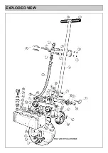
Страница 4: ...EXPLODED VIEW ...


