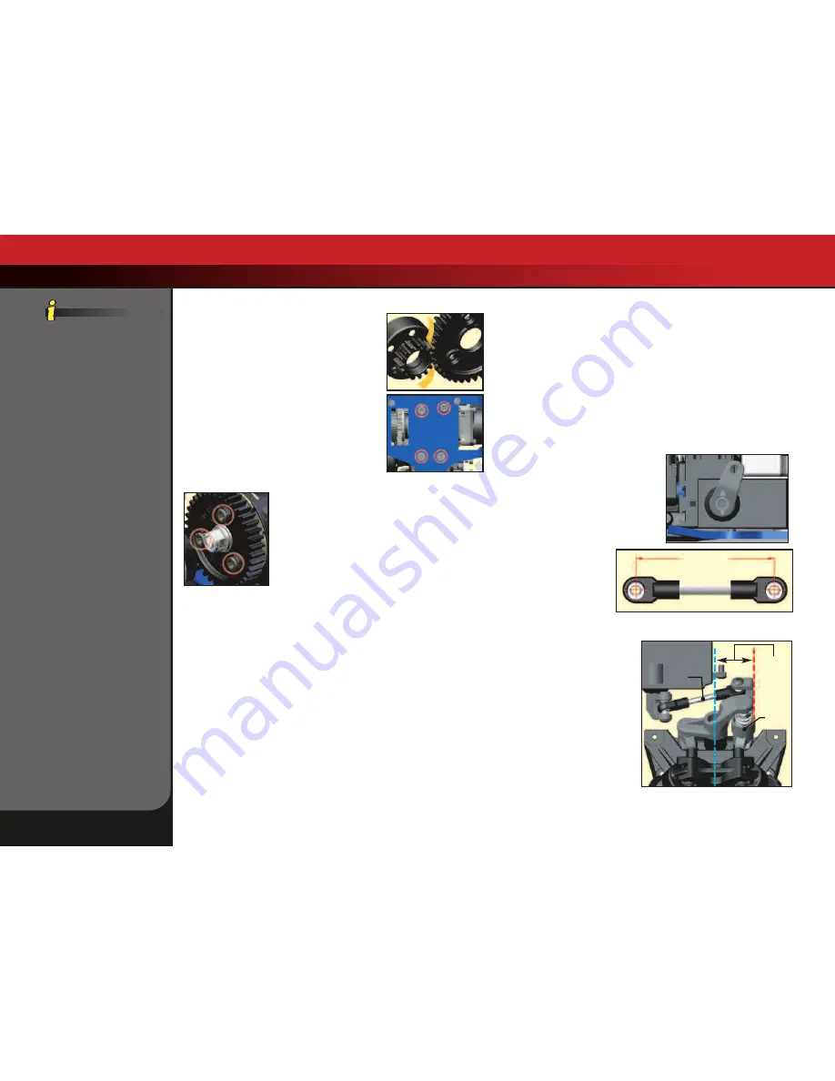
Adjusting the Spur Gear/Clutch Bell Gear Mesh
The ideal spur gear/clutch bell gear mesh for Jato is
0.1mm. To set the gear mesh, place a strip of
standard letter/A4 size copy or printer paper (about
0.1mm thick) between the mating teeth. Loosen
the four engine mount screws from the bottom
side of the chassis (see image) and slide the engine
mount up to push the clutch bell gear against the
spur gear so the paper is not too tight to pull out or
too loose that it will fall out. Tighten the engine
mount screws securely. When the paper is
removed, you should feel only the slightest amount
of play between the gears (almost none) and there
should be no binding or friction.
Changing the Spur Gear
Remove the three screws on the slipper clutch
assembly using a 2.5mm hex wrench. Slide the spur
gear off of the slipper shaft. If the spur gear is too tight
on the shaft, gently pry on the back of the gear with a
flat screw driver to loosen it.
Repeat the above steps in reverse order to install the
new spur gear. If the new spur gear is a different size,
then the engine mount screws will need to be
loosened to readjust the gear mesh (see above).
Steering System
Jato has a very sophisticated bellcrank steering system with geometry that is
designed to completely eliminate bump steer. Bump steer occurs when the
steering angle of the front wheels changes as the suspension moves up and
down through its range of travel. Suspensions that have bump steer make it
difficult to drive in a straight line over bumpy terrain. Jato tracks true no matter
how rough the course gets. An adjustable integrated servo saver protects the
servo gears and still permits precise feel and tight steering response.
Adjusting the Servo Saver
The servo saver can be adjusted by tightening or loosening the nut above the
servo saver spring. Tightening the spring will reduce the servo saver action
and provide more solid steering, especially in extremely rough environments.
However, as the servo saver spring is tightened, protection for the servo gears
is reduced. Consider tightening the servo saver spring when using more
powerful aftermarket steering servos, or servos that have metal gears.
Steering System Linkage
Precise installation and adjustment of the steering linkage is necessary to
maintain the proper factory geometry in the steering system. If you change
the steering servo or disassemble the steering linkage please follow these
instructions carefully.
Properly positioning the servo horn onto the servo shaft and carefully
setting the linkage length is required to maintain the correct steering
throw. Use the following procedure.
1.
With new or freshly charged batteries installed, turn on the transmitter
power switch followed by the receiver power switch.
2.
Set the steering trim on the transmitter to neutral (zero).
3.
Position the Jato so it is level and you can view the installed steering
servo from the front.
4.
Verify that the servo horn is positioned
so the arrow inscribed on the face
points straight up (see illustration).
5.
If it is not, remove the servo horn (by
removing the 3x6mm screw), rotate it
to the correct angle, (arrow pointing
up), and reinstall.
The steering servo link must
be assembled as shown in
the illustration below. Note
that the rod end on one end
of the steering link is rotated
45 degrees compared the
other rod end. The exact
center-to-center distance between
the hollow balls is 43.1mm.
When the steering link is installed
in the Jato, the edge of the left
bellcrank (servo saver arm) should
be parallel to the centerline of the
vehicle (see illustration). If it is not
parallel, adjust the length of the
steering link.
38 • Jato 3.3
Basic Tuning Adjustments
Steering Link Length Template
(actual size)
43.1mm
Optional servo horns are
available separately for use
with non-Traxxas servos.
Servo
Saver
Arm
Steering
Link
Parallel
Содержание 5509
Страница 1: ...owners manual MODEL 5509 ...
Страница 47: ......
Страница 48: ...owners manual 1 100 Klein Road Plano Texas 75074 1 888 TRAXXAS 060515 MODEL 5509 ...


