Installation
(qualified installers only)
7
© Travis Industries, Inc.
5/21/20 - 1534
Tempest Lantern 24v
Recommended Order of Installation
1. Determine the location of Lantern. Make sure all clearances are met, (see page 8).
2. With the Lantern head location identified, prepare and mount the Lantern head support (pillar,
post, or wall mount). This order of installation may need to be modified due to individual
installation conditions. NOTE: sections 4, 5, 6 and 7 of this page detail gas and electrical
connections to the Lantern head.
3. GAS SUPPLY: The Lantern requires 20,000 BTU input (natural gas or LP). A shut off valve and
12 inches of flex line are provided to assist connection from the supply line to the Lantern head.
The shutoff valve accepts ½” MPT (male pipe thread). Before turning gas on to the Lantern, leak-
test all gas line connections.
4. ELECTRICAL SUPPLY: The power supply must be routed through a switch to turn the Lantern
on and off (see page 10). Multiple Lanterns may be placed on a single circuit. Each Lantern
uses 24VAC at approximately 1.6 amps - make sure the circuit and wiring is appropriately sized
(see diagram on pg 12.). If multiple Lanterns are powered through a single switch, the control
modules for each of the individual Lanterns may be daisy-chained together (make sure polarity is
correct, see pg. 16). Make sure to leave slack in the electrical line so the head can be removed
for service.
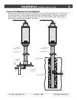
5. For outside post and pillar installations route a ½”stainless steel flexible gas line from the shut off
valve to the Lantern head (you will have to provide this gas line).
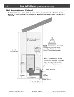
For wall mount applications; if using flex line to pass through the wall of a building the flex line
must be enclosed in conduit for protection, or local code may require you to hard pipe the
connection from the control module to the Lantern head.
6. Attach the Lantern head to the mount. Attach the gas line. Attach the 24vac electrical supply.
Leave the control covers loose to allow for leak testing access. Install the Lantern assembly (see
page 18).
7. Bleed the gas line and start the Lantern by switching on the electrical power to the control
module. Leak test the gas lines. Verify the Lantern works correctly and there are no gas leaks.
Attach the control covers.
8. Give the manual to the home owner and explain the operation of the Lantern.


