background image

 Optional 

Equipment 

41 

© Travis Industries 

93508061 

4050526 

Outside Air Installation (for wood stoves only) 

This pedestal has an internal air duct that may be used to direct air to the combustion chamber.  Follow 

the directions below prior to installing the stove or attaching the pedestal.   


Outside air is required for 

mobile home

 installations and in certain localities. Read the section "Outside 

Air Requirements" on page 11 prior to installing outside air. 

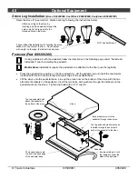
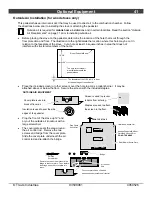
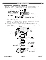
  Before placing the stove on the pedestal, determine the location of the hole that is cut through the 

floor protection and floor.  The illustration to the right details the location where this hole may be cut in 

relation to the faceplate of the stove.  Cut a hole at least 16 square inches in area that does not 

interfere with structural members of the home. 


  Place the included screen (or other screen) over the hole to act as a rodent barrier.  It may be 

attached above or below the floor.  Secure the screen with the included staples. 


  Prop the front of the stove up 12" and 

pry out the outside air knockout with a 

large screwdriver.  

  The cover plate seals the area around 

the air control rod.  Remove the two 

screws and bridge from the cover plate.  

Slide the cover plate underneath the air 

control rod and re-attach the bridge. 


The hole for outside air 
must fall underneath the 
pedestal base.

19-3/4"

26"

The faceplate of the 1190 is 3/4" in front 
of the front edge of the pedestal

Size of Pedestal Base

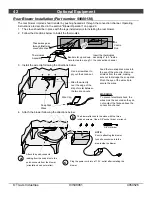
OUTSIDE AIR EQUIPMENT

Staples are used to attach 

the screen to the floor.

Screen is used to prevent 

rodents from entering.

Insulation is used to seal the side 

edges of the pedestal .

Cover plate is used to 

block off room air .

Outside Air Knock-Out

Drop Chute 
Knock-Out

Rear Blower Knock-Outs

Ashpan Pedestal/Air Boot 
Outside Air Knock-Out 
DO NOT REMOVE

FRONT OF STOVE

The cover plate has a clip which 
attaches it underneath the air control.

Remove the two screws that hold the 
bridge to the cover plate.  Then replace 
the bridge when the cover plate is in 
place.

Air Control 
Rod

Bridge

Phillips 
Screwdriver

Содержание Avalon Olympic

Страница 1: ...erence SAFETYNOTICE If this appliance is not properly installed a house fire may result For your safety follow the installation directions Contact local building or fire officials about restrictions and installation inspection requirements in your area Owner s Manual Copyright 2007 T I 10 00 93508061 4050526 Listed OMNI Test Laboratories Inc Beaverton Oregon Tested to U L 1482 Report 028 S 27 2 Ju...

Страница 2: ...oyable experience We offer our continual support and guidance to help you achieve the maximum benefit and enjoyment from your appliance Important Information No other Avalon Olympic appliance has the same serial number as yours The serial number is stamped onto the label on the back of the appliance This serial number will be needed in case you require service of any type Model Avalon Olympic Seri...

Страница 3: ...nts 20 Masonry Fireplace Requirements 20 Drafting Performance 21 Leveling Bolt Installation 21 Block Off Plate Installation 22 Insert with Positive Connection 23 Insert with Direct Connection Masonry Fireplace 23 Operating Your Appliance Safety Notice 25 Before Your First Fire 25 Opening the Door 25 Bypass Operation 26 Starting a Fire 27 Adjusting the Burn Rate 28 Ash Removal 28 Optional Blower Op...

Страница 4: ...liance Young children should be supervised when they are in the same room as the appliance Keep furniture drapes curtains wood paper and other combustibles a minimum of 36 away from the front of the appliance This appliance must be properly installed to prevent the possibility of a house fire The instructions must be strictly adhered to Do not use makeshift methods or compromise in the installatio...

Страница 5: ...mbustion air Allow the appliance to cool before carrying out any maintenance or cleaning Overfiring the appliance may cause a house fire If a unit or chimney connector glows you are overfiring Maintain the door and glass seal and keep them in good condition Avoid placing wood against the glass when loading Do not slam the door or strike the glass Do not use a grate or other device to elevate the f...

Страница 6: ...eet 1 500 to 2 500 Maximum BTU s per Hour Cord Wood Calculation 74 300 Overall Efficiency Oregon Method 70 0 Maximum Burn Time Up to 12 Hours Heating capacity will vary depending on the home s floor plan degree of insulation and the outside temperature It is also affected by the quality and moisture level of the fuel Dimensions Figure 1 Emissions 2 6 Grams Per Hour EPA Phase II Approved Tests cond...

Страница 7: ...on Legs or Pedestal Packing List Top Air Chamber Extension used for inserts only 4 Screws for the Top Air Chamber Extension Damper Rod for the Top Air Chamber Extension Pull Tool used to adjust the damper when hot Stove Installation Considerations The table below details the six most common types of installations and the considerations for each type Alternative methods of installation are availabl...

Страница 8: ...s listed below drywall furniture etc Clearances The following clearances must be met see Figure 2 and Figure 3 Minimum Clearance Singlewall Connector Reduced Clearance A Sidewall to stove 16 16 B Backwall to stove 15 10 C Cornerwall to stove 9 1 2 7 1 2 D Connector to sidewall 27 1 2 27 E Connector to backwall 17 1 2 12 F Connector to cornerwall 20 1 2 18 Reduced clearance installations require on...

Страница 9: ... top Measure front clearances from the face of the stove unibody Clearance A NOTE vent diameter varies depending on brand and model Clearance D Clearance E Clearance B Back Wall Side Wall Floor Protection 29 3 8 16 Min 6 Min 6 Min 20 1 2 5 3 4 Measure rear and side clearances from the nearest edge of the stove top Measure front clearances from the face of the stove unibody NOTE vent diameter varie...

Страница 10: ...may adversely affect draft Travis Industries can not be responsible for external forces leading to less than optimal performance Standard residential installations may use single wall connector Mobile Homes may not Standard residential installations with reduced clearance connector may use the clearance determined by the manufacturer of the connector for the connector to wall clearance or the clea...

Страница 11: ...fs Flat Roofs Chimney must extend 3 above the roof Chimney must extend 2 above any portion of the roof within 10 of the chimney Chimney must extend 3 above the roof Chimney must extend 2 above any portion of the roof within 10 of the chimney Optional Air Duct must not be longer than 15 and at least 16 square inches in cross section A hole must be cut through the floor protection and floor and the ...

Страница 12: ...ves are classified as combustible or non combustible Non combustible alcoves must have walls and a ceiling that are 3 1 2 thick of a non combustible material brick stone or concrete see Figure 7 This non combustible material must be spaced and ventilated at least 1 off of all combustible materials walls ceiling etc to allow air to move around the non combustible walls and ceiling All other alcoves...

Страница 13: ...bove Reduced Clearance Connector A Sidewall to stove 16 B Backwall to stove 10 C Cornerwall to stove 7 1 2 D Connector to sidewall 27 E Connector to backwall 12 F Connector to cornerwall 18 If using offsets use the connector clearance listed in Figure 9 not the connector manufacturer s clearance The appliance must be secured to the floor consult your building official Secure the outside air boot t...

Страница 14: ... details Floor Protection See the section Floor Protection Requirements for more details Follow the chimney manufacturer s instructions and clearances for floor penetrations A ceiling support is required an attic insulation shield is required where insulation is present Insulation Chimney Cap See the section Chimney Termination Requirements for more details Chimney Sections Minimum Air Space to Co...

Страница 15: ... for roof penetrations A storm collar and flashing are required some require a radiation shield Stove Clearances See the section Stove Placement Requirements for more details Follow the chimney manufacturer s instructions and clearances for wall penetrations A wall radiation shield thimble is required Optional insulated chase Wall Bands and Supports Insulated Tee with cleanout Minimum 15 Maximum 3...

Страница 16: ...ged and meet all local building codes UBC etc Damage must be repaired prior to installation The chimney must be 15 to 33 tall Clay Liner Floor Protection See the section Floor Protection Requirements for more details Combustible Mantle Min 18 See the section Stove Placement Requirements for minimum clearances required Max 8 Make sure the clean out seals in place Clay Liner See the section Stove Pl...

Страница 17: ...ce The fireplace insert can be lightened by removing the firebricks and baffle pg 36 replace before operation Additional Accessories Needed for Installation x Surround Panels see page 44 Standard vs Cook Top Installations The top air chamber extension is shipped separately with the heater see the following page for details When installed the unit is considered a Standard Model for Insert Placement...

Страница 18: ...the grill Remove and discard the bypass extension rod keep the pull ring 2 Install the top air chamber extension following the directions below 3 Attach the grill to the air chamber top Attach the bypass extension rod included in the owner s kit to the damper yoke Attach the bypass pull ring to the extension rod to complete the installation Phillips Screwdriver Remove the grill Remove and discard ...
Страница 19: ...ook Top Model Minimum Fireplace Size a b c d e f g h i j Height front Height rear Width front Width rear Depth Hearth Depth Hearth Width Facing Width Facing Height with Mantel Shield Mantel Height with Mantel Shield 22 1 4 22 1 4 29 3 8 29 3 8 14 1 8 22 3 8 45 3 8 56 3 8 51 1 4 38 1 4 53 1 4 40 1 4 This is the distance the insert protrudes from the fireplace opening plus the required 16 of hearth ...

Страница 20: ...nts Chimney must have a clay tile liner or a stainless steel liner positive connection Entire fireplace including chimney must be clean and undamaged Any damage must be repaired prior to installation of the insert Chimney height 15 minimum 33 maximum Entire fireplace including chimney must meet local building requirements Side Wall Combustible Mantel Combustible Top Facing Non Combustible Hearth F...

Страница 21: ...timal performance Leveling Bolt Installation Two leveling bolts are included to level the insert if the fireplace has a stepped up hearth To install raise the rear of the insert up and insert the leveling bolts into the holes in the rear corners of the insert Adjust the bolts until they extend the same height as the hearth steps up After the insert is installed fine tune the leveling bolts to leve...

Страница 22: ...s on the template and place it inside the fireplace If the template fits correctly in its planned location go to the next step If it does not make a new template with the appropriate corrections until it fits correctly With the template in place mark the location of the flue see Dimensions on page 6 This location approximates the center of the flue when the insert is in place a slight offset may o...

Страница 23: ...tion and support Remove damper or wire it open Airtight Insulated Clean Out Combustible Mantle Flue Liner See the section Insert Placement Requirements for minimum clearances and hearth required Cap prevents water from entering Install a non combustible cover plate to prevent water from entering the chimney Surround Panels Block off plate or damper adapter Remove damper or wire it open Airtight In...

Страница 24: ...sed with a masonry fireplace only The requirements in the section Masonry Fireplace Requirements must be fulfilled prior to installation Flue Liner See the section Insert Placement Requirements for minimum clearances and hearth required Surround Panels with insulation see Surround Panels installation instructions in the back of the manual NOTE It is recommended your chimney have a minimum 28 and a...

Страница 25: ...ket The door gasket might adhere to the paint on the front of the heater Leave the door slightly ajar for the first fire and be careful when opening the door after the first fire Over Firing the Stove This stove was designed to operate at a high temperature But due to differences in vent configuration fuel and draft this appliance can be operated at an excessive temperature If the stove top or oth...

Страница 26: ...lue creating more draft When pushed in the smoke goes around the baffle utilizing the secondary combustion and making the heater more efficient When starting or re loading pull the bypass out During normal operation push the bypass in Bypass Pushed In Used for normal operation Bypass Pulled Out Used for starting and re loading Use the included pull tool to operate the bypass rod ...

Страница 27: ...r use gasoline gasoline type lantern fuel kerosene charcoal lighter fluid or similar liquids to start or freshen up a fire in this stove Keep all such liquids well away from the stove while it is in use If using a firestarter use only products specifically designed for stoves follow the manufacturer s instructions carefully If the smoke does not pass up the chimney ball up one sheet of newspaper p...

Страница 28: ... control may take several minutes to influence the burn rate When making adjustments you may wish to let the stove burn for 10 minutes to gauge performance Ash Removal Ashes should be placed in a metal container with a tight fitting lid The closed container of ashes should be placed on a noncombustible floor or on the ground away from all combustible materials pending final disposal If the ashes a...

Страница 29: ... overnight burn 1 Move the air control to high burn and let the stove become hot burn for approximately 15 minutes 2 Load as much wood as possible Use large pieces if possible 3 Let the stove burn on high for 15 minutes to keep the stove hot then turn the air control to low 4 In the morning the stove should still be hot with embers in the coal bed Stir the coals and load small pieces of wood to re...

Страница 30: ... less creosote Testing Wood Moisture Split wood stored in a dry area will be fully dry within a year This insures dry wood If purchasing wood for immediate use test the wood with a moisture meter Some experienced wood burners can measure wood moisture by knocking pieces together and listening for a clear knock and not a thud Why Dry Wood is Key Wet wood when burned must release water stored within...

Страница 31: ...ect draft In these cases a small amount of smoke may enter the home Adding more pipe or a draft inducing cap may help Stove Does Not Burn Hot Enough Wood is Wet see the section Selecting Wood on page 30 for details on wood Make sure the air control is all the way open Slide the control back and forth to insure the control is not stuck Insufficient Draft Chimney height and outside conditions can ne...

Страница 32: ...l combustible materials pending final disposal Improperly disposed ashes lead to fires Hot ashes placed in cardboard boxes dumped in back yards or stored in garages are recipes for disaster Wood burning stoves are inherently dirty During cleaning have a vacuum ready to catch spilled ash make sure ash is entirely extinguished There are vacuum cleaners specifically made to remove ash even if the ash...

Страница 33: ...accumulates on the flue lining When ignited this creosote makes an extremely hot fire The chimney and chimney connector should be inspected at least once every two months during the heating season to determine if a creosote buildup has occurred If creosote has accumulated it should be removed to reduce the risk of a chimney fire If you are not certain of creosote inspection contact your dealer or ...

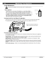
Страница 34: ...ting odors The optional blower should be vacuumed every year to remove any buildup of dust lint etc Firebrick and Baffle Inspection Use the illustration on page 36 as a reference for checking the following items Make sure the appliance is cool before proceeding Baffle Firebricks check the bricks along the ceiling of the firebox to make sure they are intact and have no gaps between them Slide the b...

Страница 35: ...he glass clip gaskets adhere to the glass clips Remove the glass Place the glass gasket in the inner channel of the door shell then place the glass on top of the gasket Replace the clips to secure Replacing the Door Gasket The door gasket inserts into the outer groove of the door shell Stove gasket cement holds it in place Before installing remove any residual cement Lay the gasket in place start ...

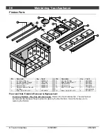
Страница 36: ...8900338 8 Damper Yoke 1 98900326 9 Damper Extension Rod with Pull Ring 1 98900334 10 Brick 9 x 4 5 un cut 21 175 00001 1 99900102 8 11 Brick Cut 8 25 x 4 5 2 251 00010 12 Brick Cut 6 25 x 4 5 2 251 00011 Floor and Side Firebrick Removal Replacement Do not pry firebrick they chip and crack easily Remove the floor firebricks first The side firebrick are removed later because they are pinned in place...

Страница 37: ...he rear secondary air tube and rear air channel 6 Slide the damper slider all the way forward 7 Reach into the firebox and push up on the damper yoke until the damper yoke separates from the damper slider Remove both the damper slider and damper plate by sliding them between the front two secondary air tubes REPLACEMENT INSTRUCTIONS 1 Place the damper plate above the secondary air tubes in the rea...

Страница 38: ...r or weather damage which is the result of but not limited to improper chimney venting installation 7 Exclusions to this 7 Year Warranty include injury loss of use damage failure to function due to accident negligence misuse improper installation alteration or adjustment of the manufacturer s settings of components lack of proper and regular maintenance damage incurred while the appliance is in tr...

Страница 39: ...REQUIREMENTS A SIDEWALL TO UNIT B BACKWALL TO UNIT C CORNER TO UNIT D SIDEWALL TO CONNECTOR E BACKWALL TO CONNECTOR F CORNERWALL TO CONNECTOR STANDARD RESIDENTIAL INSTALLATION SINGLEWALL CONNECTOR 16 15 9 5 27 5 17 5 20 5 MOBILE HOME ALCOVE AND REDUCED CLEARANCE INSTALLATIONS REQUIRES DOUBLE WALL CONNECTOR 16 10 7 5 27 12 18 STOVE FLOOR PROTECTOR 6 MIN 6 MIN 16 MIN 45 S T O V E ADJACENT WALL ADJAC...

Страница 40: ...ress nuts on the bottom of the stove with the two attachment brackets on the pedestal Insert the two bolts with washers through the brackets on the pedestal and into the stove Tighten the bolts with a 9 16 wrench Attach each leg to the stove by inserting a bolt and washer through the hole or slot in the leg and into the threaded hole on the stove 9 16 Socket Wrench These rubber tipped bolts are fo...

Страница 41: ...elow the floor Secure the screen with the included staples Prop the front of the stove up 12 and pry out the outside air knockout with a large screwdriver The cover plate seals the area around the air control rod Remove the two screws and bridge from the cover plate Slide the cover plate underneath the air control rod and re attach the bridge The hole for outside air must fall underneath the pedes...

Страница 42: ...embly 4 to 5 inside the convection channel Slide the wire clip over the edge of the strip of metal between the two knock outs Feed the two snap disk wires into the eye of the wire clip Remove all slack from the wire making sure not to dislodge the snap disk Pinch the eye of the wire clip to secure the wires Wire Clip Snap Disk Wires WARNING To prevent electrical shock the wires must be secured so ...

Страница 43: ... to the stove 5 Slide the lower section down until it contacts the hearth Attach the two sections together following the directions below The cover plate has a clip which attaches it underneath the air control Remove the two screws on the cover plate to remove the piece that fits over the air control rod Then replace the piece when the cover plate is in place Air Control Rod Bottom of Stove 8 7 8 ...

Страница 44: ...overlaps the fireplace opening to form a seal between the panels and the fireplace face Let the silicon or cement dry 2 Push the insert into the fireplace allowing the insulation to form a seal between the panels and the fireplace Use a screwdriver to tuck any exposed insulation behind the panels Avalon Pendleton 45 and Rainier 45 Remove the brass trim along the top of the stove Button Plugs pry o...

Страница 45: ...tom with a pair of slip joint pliers Disconnect the molex plug inside the blower assembly Remove the power cord by pulling it out of the hole exposed by removing the strain relief Remove the button plug from the left side and insert it into the hole on the right side Left Side of Blower Assembly The wires tuck in here directly behind the blower cage Button Plug for Air Control Rod For the Rainier ...

Страница 46: ... Fire Starting 26 Firebox Assembly 36 Firebox Parts 36 Firebrick and Baffle Inspection 34 Firebrick Removal Replacement 36 Floor Protection Requirements stove 8 Glass Cleaning 32 Glass Replacement 35 Hearth Floor Protection Stove 8 Hearth Stove 16 Heating Specifications 6 Hints for Burns 30 Installation Options 6 Installation stove 7 Leg Installation 40 Listing Label 39 Maintenance 32 Mobile Home ...

Отзывы: