3
DIVERSITY A
POWER
RF SIGNAL
LEVEL
AUDIO
OUTPUT XLR
AC
ADAPTOR
INLET
16 CHANNEL
SELECTOR SWITCH
AUDIO
OUTPUT JACK
AUDIO
OUTPUT
LEVEL
MUTE/
SQUELCH
CONTROL
AF PEAK O/L
DIVERSITY B
{
ANTENNA B
ANTENNA A
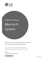
S4.16
RECEIVER
LAYOUT
RECEIVER OPERATION
1. Connect the appropriate AC adaptor into the DC inlet as marked on the
rear panel and observe the Supply indicator (green Led ) lights up.
2. To provide best diversity operation, attach the antennae and angle them
to form a ”V” (as per illustration) ensuring they have a good line-of–sight
view of the corresponding transmitter. i.e. Avoid placing large metallic
objects in the transmission path.
3. Initially set the receiver AF gain control to its mid-position and connect
the AF output from either the
1/4
inch Jack or XLR to your Mixing console
or amplifier.
4. Select rear panel Channel Selector Switch (Small screw-driver adjust)
to correspond to Transmitter setting. It is possible to select any of the 16
channels. (
Factory set to position 1
).
S4.16 ARTWORK_final_1 colour 20/10/06 08:27 Page 7