P
RO
L
INE
C
ONNECTION
I
NSTRUCTIONS
2
98
‐
0019
‐
57
•
REV
1703.20
C
ONNECTIONS
,
S
TARTUP
&
P
OWER
D
OWN
WARNING!
DO NOT start the ProLine PC/Laptop. All cables must be
connected and equipment must be
powered up and powered
down in a specific order
. Otherwise, loss of DVI configuration
settings could occur.
A.
C
ONNECT
C
ABLES
Refer
to
one
of
the
following
diagrams
that
match
your
equipment
and
connect
all
cables:
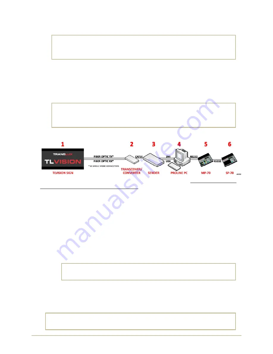
TL
Vision
/
Fiber
Optic
/
Epic
/
ProLine
–
refer
page
5.
TL
Vision
/
Fiber
Optic
/
Epic
/
ProLine
/
MP
‐
70
–
refer
to
page6.
TL
Vision
/
Fiber
Optic
/
Epic
/
ProLine
/
MP
‐
70
/
SP
‐
70
–
refer
to
page
7.
WARNING!
DO NOT start the ProLine PC/Laptop. All cables must be
connected and equipment must be
powered up and powered
down in a specific order
. Otherwise, loss of DVI configuration
settings could occur.
B.
S
TARTUP
To
prevent
any
possible
loss
of
pre
‐
programmed
configuration
settings
it
is
very
important
to
turn
on
the
equipment
in
the
following
specific
order
:
1.
Turn
ON
the
TLVision.
2.
Turn
ON
the
Transceiver/Converter.
3.
Turn
ON
the
Sender
Box
[and
Video
Processor
if
present].
4.
Turn
ON
the
ProLine
PC/Laptop.
TLVision
sign
should
display
the
following:
a.
Blue
screen
–
Windows
is
loading.
b.
Black
screen
–
wait
several
seconds
until
ProLine
starts
and
loads
message.
NOTE
:
ProLine
is
set
at
the
factory
to
start
automatically
but
if
it
does
not
then
manually
start
ProLine.
c.
Display
Message
–
ProLine
displays
the
default
message.
5.
Turn
ON
the
MP
‐
70.
WARNING!
Powering up the MP-70 ahead of the ProLine PC/Laptop may cause
the ProLine PC/Laptop to load the MP-70 as a mouse or pointing
device.
6.
Turn
ON
the
SP
‐
70.
C.
P
OWER
D
OWN
I
N
R
EVERSE
O
RDER
Power
down
in
reverse
order
.
Wait
until
the
ProLine
PC/Laptop
is
completely
powered
down
before
turning
off
the
Video
Processor,
Sender,
and
TLVision
Sign.
WARNING!
Wait until the ProLine PC/Laptop is completely powered down
before turning
off the Sender, Video Processor and TLVision Sign. Otherwise, loss of DVI
configuration settings could occur.
Содержание TL Vision
Страница 1: ...TL VISION TL VISION EPIC PROLINE MESSAGE CONTROLLER CONNECTION INSTRUCTIONS PN 98 0019 57 REV 1703 20 ...
Страница 4: ...PROLINE CONNECTION INSTRUCTIONS IV 98 0019 57 REV 1703 20 This page intentionally left blank ...
Страница 7: ...98 0019 57 REV 1703 20 3 PROLINE CONNECTION INSTRUCTIONS WIRING DIAGRAMS TL VISION CAT5 EPIC PROLINE ...
Страница 8: ...PROLINE CONNECTION INSTRUCTIONS 4 98 0019 57 REV 1703 20 TL VISION CAT5 EPIC PROLINE ...
Страница 9: ...98 0019 57 REV 1703 20 5 PROLINE CONNECTION INSTRUCTIONS TL VISION FIBER OPTIC EPIC PROLINE ...
Страница 10: ...PROLINE CONNECTION INSTRUCTIONS 6 98 0019 57 REV 1703 20 TL VISION FIBER OPTIC EPIC PROLINE MP 70 ...
Страница 11: ...98 0019 57 REV 1703 20 7 PROLINE CONNECTION INSTRUCTIONS TL VISION FIBER OPTIC EPIC PROLINE MP 70 SP 70 ...
Страница 16: ...PROLINE CONNECTION INSTRUCTIONS 12 98 0019 57 REV 1703 20 NOTES ...


