6
13
PowerStar™ III
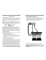
Optionally Setting Pin Jumpers
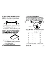
NOTE: The default factory setting makes pins 3 & 4 active in the RJ-11
connector and pins 4 & 5 active in the RJ-45 connector.
NOTE: Since pin jumpers are located inside the PowerStar III, the
PowerStar™ III cover must be removed when setting the pin jumpers.
WARNING: DISCONNECT POWER CORD from PowerStar™ III
before setting jumper pins. Failure to observe this warning could result
in personal injury or death from electrical shock.
WARNING: AVOID CONTACT WITH POWER SUPPLY during jumper
pin setting. Failure to observe this warning could result in personal
injury from electrical shock caused by capacitive discharge.
CAUTION: Wear a grounding device and observe electrostatic
discharge precautions when setting pin jumpers. Use needle nosed
pliers with insulated handle. Failure to observe this caution could
result in circuit board failure.
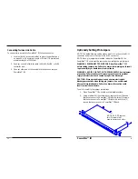
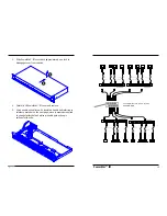
To verify or modify the jumper pin settings:
1. Place PowerStar™ III on table or other stable surface.
2. Using medium Phillips screwdriver, remove three (3) screws
that secure cover to PowerStar™ III left side, three (3) screws
that secure cover to PowerStar™ III right side, and three (3)
screws that secure cover to PowerStar™ III back.
NOTE: Do NOT remove
two (2) screws that
secure power connector.
Connecting Twinax Link Cable
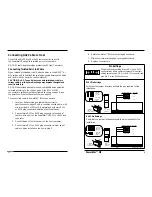
To connect twinax cable to PowerStar™ III twinax connector:
1. Locate or build twinax cables that conform to specifications
on page 20, with minimum length of 25 feet (7.6 meters) and
maximum length of 5000 feet.
2. Connect one end of twinax cable to AS/400, Sys/36, or 5x94
controller port.
3. Connect other end of twinax cable to twinax connector on
PowerStar™ III.

