
PowerStar™ III
20
CAUTION: RJ connectors are NOT INTENDED FOR
CONNECTION TO THE PUBLIC TELEPHONE
NETWORK. Failure to observe this caution could result
in damage to the public telephone network.
Compliance Information
UL Listed
C-UL Listed (Canada)
CISPR/EN55022 Class A
FCC Regulations
This equipment has been tested and found to comply with the limits for a class
A digital device, pursuant to part 15 of the FCC rules. These limits are
designed to provide reasonable protection against harmful interference when
the equipment is operated in a commercial environment. This equipment
generates, uses, and can radiate radio frequency energy and, if not installed
and used in accordance with the instruction manual, may cause harmful
interference to radio communications. Operation of this equipment in a
residential area is likely to cause harmful interference, in which case the user
will be required to correct the interference at the user’s own expense.
Canadian Regulations
This digital apparatus does not exceed the Class A limits for radio noise for
digital apparatus set out on the radio interference regulations of the Canadian
Department of Communications.
European Regulations
Warning
This is a Class A product. In a domestic environment this product may cause
radio interference in which case the user may be required to take adequate
measures.
Copyright Restrictions
© 1994, 1996 TRANSITION Networks Inc.
All rights reserved. No part of this work may be reproduced or used in any
form or by any means – graphic, electronic, or mechanical – without written
permission from TRANSITION Networks Inc.
Trademark Notice
All registered trademarks and trademarks are the property of their respective
owners.
Der Anschluss dieses Gerätes an ein öffentlickes
Telekommunikationsnetz in den EG-Mitgliedstaaten verstösst gegen die
jeweligen einzelstaatlichen Gesetze zur Anwendung der Richtlinie
91/263/EWG zur Angleichung der Rechtsvorschriften der
Mitgliedstaaten über Telekommunikationsendeinrichtungen
einschliesslich der gegenseitigen Anerkennung ihrer Konformität.
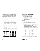
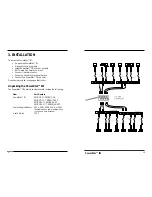
Twinax Cable and Connector Specifications
Cable Characteristics:
Twinax cable consists of conductors - one tinned and one solid copper - in a
tinned copper braid shield, with impedance of 100 ohms.
Cable Type
IBM PN or equivalent
Twinax Plenum
7362061
Twinax PVC
7362211
Minimum Cable Distance:
Host to Product
7.6 meters (25 feet)
Product to Product
7.6 meters (25 feet)
Product to Terminal Device
not applicable
Maximum Cable Distance:
Host to Product
1500 meters (5,000 feet
)
Product to Product
1500 meters (5,000 feet
)
Product to Terminal Device
not applicable
Connector Characteristics:
Twinax connectors (IBM or equivalent) can be connected to twinax cable. (The
last twinax connection in a daisy-chain must be terminated.)
Fiber Cable and Connector Specifications
The physical characteristics of the fiber cable must meet or exceed the following:
Cable Characteristics:
Fiber Optic Cable Recommended:
62.5 / 125 µm multimode fiber
Optional:
100 / 140 µm multimode fiber
85 / 125 µm multimode fiber
50 / 125 µm multimode fiber
Fiber Optic Transmitter Power:
Average power:
-15.0 dBm
Peak power:-12.0 dBm ±1dBm
Fiber Optic Receiver Sensitivity:
Average sensitivity: -27.4 dBm
Bit error rate:
≤
10
-10
Minimum Cable Distance:
Host to Product
7.6 meters (25 feet)
Product to Product
7.6 meters (25 feet)
Product to Terminal Device
not applicable
Maximum Cable Distance:
Host to Product
3000 meters (10,000 feet
)
Product to Product
3000 meters (10,000 feet
)
Product to Terminal Device
not applicable
Connector Characteristics:
ST type connectors (SMA type available upon request)