Chapter 2: Installation
2.1 Indicator Connect
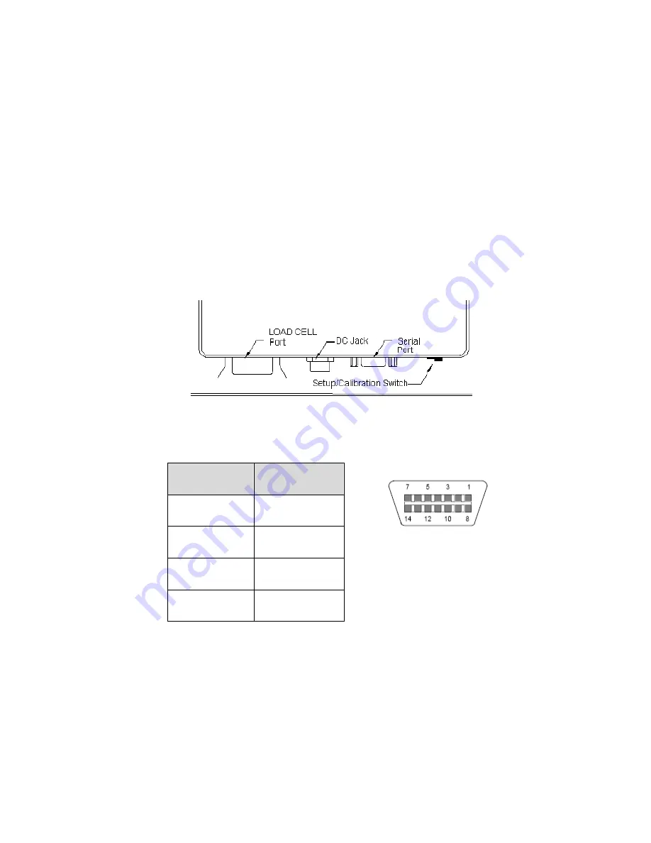
The rear panel contains all connectors necessary to make the appropriate
connections to the force gauge’s platform, printer, remote display and batch equipment.
2.1.1 Connecting the force gauge platform
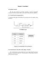
1. Plug the load cell’s cable into LOADCELL Port on the rear panel of the indicator. Show
in figure 2-2.
TI-1500B Rear Panel
Pin No.
Pin Name
1/8
+Excitation
3/10
-Excitation
5/12
+Signal
7/14
-Signal
Figure 2-2: Pin assignments for the Load Cell Port
2.1.2 Connecting the serial printer, remote display or computer
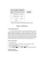
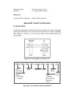
The TI-1500B indicator comes standard with one full duplex RS-232 serial port,
designed for connection to either a PC, a serial printer or a remote display. Figure 2-4
shows the serial port pinout.


