


Page 5
Accessories
•
All electrical accessories must be installed and wired according
to the instructions packaged with the accessory.
Control Wiring (Class II)
•Low voltage control wiring should not be run in the same
conduit with the power wiring unless Class I wire of the proper
voltage rating is used. Route the thermostat cable or equivalent
single leads of No. 18 AWG colored wire from the thermostat
subbase terminals through the rubber grommet on the unit. See
Figure 1 for the control entry location. Make connections as
shown on the unit wiring diagram and in Figures 5 and 6.
•Do not short thermostat wires since this will damage the control
transformer.
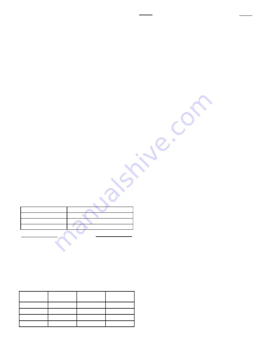
•Recommended wire sizes and lengths for installing the unit
thermostat are provided in
Table 1: Thermostat Wire Size and
Maximum Length.
The total resistance of these low voltage
wires must not exceed one (1) ohm. Any resistance in excess of one
(1) ohm may cause the control to malfunction because of the
excessive voltage drop.
•IMPORTANT: Upon completion of wiring check all elec-
trical connections, including factory wiring within the unit.
Make sure all connections are tight. Replace and secure all
electrical box covers and access doors before leaving the unit or
turning on the power to the unit.
•After all electrical wiring is complete, set the thermostat system
switch on the
OFF
position so that the compressor will not run and
then apply power by closing the system main disconnect switch.
This will activate the compressor sump heat. Do not change the
Thermostat System Switch until power has been applied long
enough to evaporate any liquid HCFC-22 in the compressor. It is
recommended that the sump heat be energized for a minimum of
eight (8) hours prior to starting the unit.
Table 1
Thermostat Wire Size and Maximum Length
WIRE SIZE
MAXIMUM LENTGH (Ft)
18
75
16
125
14
200
Table 2. Filter Data
Air Filters
•These units require filters with adequate filter area be pro-
vided in the return air duct. Table 2 below gives filter data. The
specific location of the filters depends on the type of installation
and the layout of the duct system. Be sure the owner is aware
of the location of the filter and the need to change them as
required. The Filter Size (Sq.. Ft.) are based on 300 F.P.M. face
velocity. If permanent filters are used, size per mfg. recommen-
dation with clean resistance of .05" WC.
UNIT
NOMINAL
CFM
FILTER*
(Sq Ft) SIZE
FILTER
RESISTANCE
WCK024B
800
2.67
0.05
WCK030B
1000
3.33
0.05
WCK036B
1200
4.00
0.05
WCK042B
1400
4.67
0.05
GENERAL
Operation of the unit heating and cooling cycles is automatic for
HEAT
and
COOL
functions. (The optional automatic changeover
thermostat, when in the
AUTO
position, automatically changes
to heat or cool with sufficient room temperature change.) The fan
switch can be placed in either the
ON
position, causing continu-
ous evaporator (indoor) fan operation, or the
AUTO
position
causing fan operation to coincide with heating or cooling run
cycles. Continuous fan mode during cooling operation may not be
appropriate in humid climates. If the indoor air exceeds 60%
relative humidity or simply feels uncomfortably humid, it is
recommended that the fan only be used in the AUTO mode.
COOLING MODE
(NOTE:
TSH
&
TSC
are contacts internal to the indoor thermo-
stat.)
With the disconnect switch in the
ON
position, current is
supplied to the compressor crankcase heater and control trans-
former. The cooling cycle is enabled through the low voltage side
of the control transformer to the
“R”
terminal on the indoor
thermostat. With the system switch in the
AUTO
position and
TSC-1
contacts closed, power is supplied to the
“O”
terminal on
the indoor thermostat to the switchover valve coil
(SOV)
. This
energizes the switch-over valve
(SOV)
and places it in the
cooling position (it is in the heating position when not energized).
When the indoor temperature rises 1-1/2 degrees,
TSC-2
con-
tacts close, supplying power to the
“Y”
terminal on the indoor
thermostat, and to the compressor contactor
(CC)
. This starts
the outdoor fan motor and compressor. The
TSC-2
contacts also
provide power to the
“G”
terminal which provides power to the
fan relay
(F)
and motor speed tap terminal and starting the
indoor fan motor.
HEATING MODE
With the disconnect switch in the
“ON”
position, current is
supplied to the control transformer. Starting at the
“R”
terminal
on the indoor thermostat, current goes through the system switch
(which is in
“AUTO”
position) to the
TSH-1
contacts. When
closed, these contacts supply power to terminal
“Y”
on the indoor
thermostat as well as to the heating anticipator. The switch-over
valve will not energize because of the high resistance of the
heating anticipator in the thermostat. Power is provided from
“Y”
to the compressor contactor
(CC)
which starts the outdoor
fan motor and compressor. The indoor thermostat contact
TSH-
1
also provides power to
“G”
terminal on the indoor thermostat
energizing the fan relay
(F)
, and motor speed tap terminal, which
starts the indoor fan motor
SUPPLEMENTARY HEAT
The supplementary electric heat
is brought on when the
indoor temperature drops 1-1/2 degrees below the thermostat
setting.
TSH-2
contacts close providing power to the
“W”
termi-
nal on the indoor thermostat and to the supplementary heater
control circuit.
NOTE:
The
fan relay
(F)
must have been energized.
An outdoor thermostat may have been added to disallow the
second stage (if provided) of electric heat above a selected outdoor
temperature. If the outdoor temperature falls below the setting
on the outdoor thermostat, this additional heater stage will come
on. When the outdoor air temperature rises, and the outdoor T-
stat setpoint is reached, the system will revert back to first stage
electric heating.
When the indoor ambient is satisfied,
TSH-2
contacts will open
Sequence of Operation


