


CTV-SVX009D-GB
19
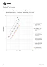
11
UNT-PRC002-GB
Sound power levels
Discharge
Measurement conditions:
Measurements taken in a room adjacent to the room containing the FWD, at the outlet of the rectangular duct (1.5 m
long) fixed to its discharge opening.
Fan
Power level in dB(A), per Hz frequency band
Overall power
Unit
speed
125
250
500
1000
2000
4000
8000
dB(A)
1
55
50
42
37
37
31
30
46
FWD 08
2
57
54
47
40
30
38
40
50
3
58
57
50
42
32
40
43
53
1
57
51
45
42
34
33
28
48
FWD 10
2
58
54
48
45
38
39
35
51
3
60
58
50
48
40
42
39
54
1
57
51
45
42
34
33
28
48
FWD 12
2
58
54
48
45
38
39
35
51
3
60
58
50
48
40
42
39
54
1
56
62
50
48
39
38
36
56
FWD 14
2
61
66
55
53
47
46
45
60
3
63
69
58
56
50
50
49
63
1
57
63
51
49
40
39
37
57
FWD 20
2
61
66
55
53
47
46
45
60
3
63
69
58
56
50
50
49
63
Intake
Measurement conditions:
Measurements taken at the horizontal air intake.
Fan
Power level in dB(A), per Hz frequency band
Overall power
Unit
speed
125
250
500
1000
2000
4000
8000
dB(A)
1
56
55
55
53
46
45
42
57
FWD 08
2
63
62
60
60
53
53
53
64
3
66
65
63
62
56
55
57
67
1
62
58
55
58
51
48
44
61
FWD 10
2
66
63
60
62
56
55
52
66
3
70
67
63
65
59
59
57
69
1
62
58
55
58
51
48
44
61
FWD 12
2
66
63
60
62
56
55
52
66
3
70
67
63
65
59
59
57
69
1
66
65
65
65
57
50
46
68
FWD 14
2
73
72
69
71
64
59
57
74
3
78
76
73
75
69
64
63
78
1
68
72
64
64
56
52
50
69
FWD 20
2
76
76
68
71
65
61
61
75
3
78
79
71
74
69
66
66
78
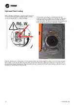
1 = Isolation valve
2 = Vibration isolators
3 = Evaporator – End view (2-pass)
4 = Evaporator Waterbox
5 = Vent
6 = Strainer
7 = Drain
Entering Chilled Water Piping
• Air vents to bleed the air from the system (to be placed
on the highest point)
• Water pressure gauges with shutoff valves
• Vibration eliminators
• Shutoff (isolation) valves
• Thermometers if desired (temperature readings
available on chiller controller display)
• Clean-out tees
• Pipe strainer
Pi = Pressure gauge
FT = Water Flow Switch
T1 = Evaporator Water Inlet Temperature Sensor
T2 = Evaporator Water Outlet Temperature Sensor
A = Isolate unit for initial water loop cleaning
B = Vent must be installed at the high point of the line
C = Drain must be installed at the low point of the line
Leaving Chilled Water Piping
• Air vents to bleed the air from the system (to be placed
on the highest point)
• Water pressure gauges with shut off valves
• Vibration eliminators
• Shutoff (isolation) valves
• Thermometers (temperature readings available on the
chiller controller display)
• Clean-out tees
• Balancing valve
• Flow Proving Device
Evaporator Piping
Evaporator Piping Components
Piping components include all devices and controls used to provide proper water system operation and unit operating
safety. A typical GVAF evaporator piping is shown below.
Figure 5 – Typical GVAF evaporator water piping
1
1
2
2
6
7
5
3
4
1
1
A
A
B
7
C


