background image

Installation

14

 CLCH-SVN05C-EN

a small air leak between the duct and the deck will destroy 
most of the attenuation available from the steel decking.

In addition, special consideration may be required to 
ensure that the weight of the unit does not crush the roof 
deck at those points where the deck is between the curb 
and support joist. Poured insulation will usually add the 
required strength, while the use of rigid insulation may 
require placement of three-inch support channels on the 
decking.

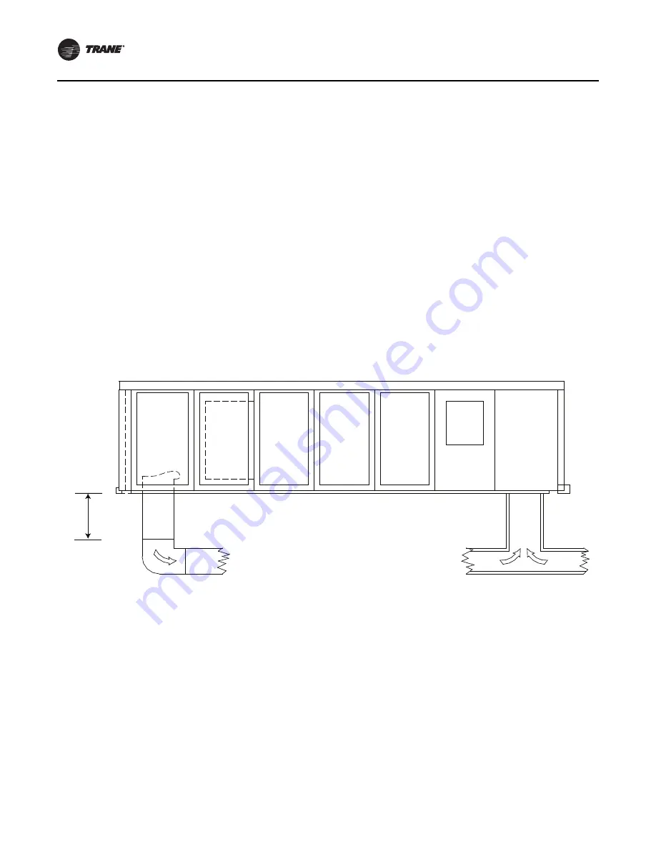
As a general rule, exhaust fan noise is not a problem and 
can be adequately attenuated by the return ductwork. For 
critical applications where return ductwork is not required, 
however, installation of an acoustically-lined “return T” is 
recommended; see 

Figure 21

.

Supply and Return Air Ductwork

Ductwork for all units must be fabricated and installed by 
the installing contractor; to ensure proper duct 
construction and installation, SMACNA recommendations 
should be closely followed.

Below are several typically used guidelines for ductwork 
construction:

Elbows with turning vanes or splitters are 
recommended to minimize air noise and resistance. 

The first elbow in the ductwork leaving the unit should 
be no closer than 3 fan diameters from the unit, 
thereby minimizing noise and resistance.

In those instances where the unit is installed over an 
acoustically critical area, additional treatment of the 
ductwork is recommended. Both supply and return 

ductwork should be lined internally with glass fiber duct 
liner 1-inch thick. The external surface of the supply duct 
should be covered with an acoustical barrier material such 
as one or two pound/sq. ft. sheet lead (1/64-inch or 1/32-
inch) or loaded vinyl sheet or gypsum board for the first 10 
ft. of ductwork. The lining should extend from the point 
where the duct penetrates the roof to a distance of 10 ft. 
beyond the vertical drop from the unit.

Figure 21.

Typical supply and return ductwork

Coil 
space

Vertical
discharge

3 fan

diameters

Return

air

Use lined duct for all returns (1-inch thick, 6-pound density fiberglass recommended).

Содержание CSAA

Страница 1: ...nowledge and training Improperly installed adjusted or altered equipment by an unqualified person could result in death or serious injury When working on the equipment observe all precautions in the literature and on the tags stickers and labels that are attached to the equipment Installation Instructions Roof Curbs for Performance Climate Changer Air Handlers Model CSAA and PSCA X 39641204010 CLC...

Страница 2: ...uation which if not avoided could result in minor or moderate injury It could also be used to alert against unsafe practices NOTICE Indicates a situation that could result in equipment or property damage only accidents WARNING Proper Field Wiring and Grounding Required Failure to follow code could result in death or serious injury All field wiring MUST be performed by qualified personnel Improperl...

Страница 3: ... the trademarks of their respective owners Revision History Updated dimensional data WARNING Follow EHS Policies Failure to follow instructions below could result in death or serious injury All Ingersoll Rand personnel must follow Ingersoll Rand Environmental Health and Safety EHS policies when performing work such as hot work electrical fall protection lockout tagout refrigerant handling etc All ...

Страница 4: ...ite Preparation 6 Roof Curb Installation Checklist 6 Dimensions and Weights 7 Installation 8 Placement 8 Assembly and Installation 10 Unit Roof Curb 10 Pipe Cabinet Roof Curb 12 Specialty Roof Curbs 12 Ductwork Recommendations 13 Sound Attenuation 13 Supply and Return Air Ductwork 14 Parts Information 15 ...

Страница 5: ...e installation and startup difficulties Nameplate Each air handler section includes at least one nameplate label which identifies the type of section and functional components customer tagging information the unit serial number the unit order number the build section position for installation and the unit model number Refer to this information when ordering replacement parts or requesting service ...

Страница 6: ...o calculate the total curb weight find the unit length multiply by the factor supplied in Table 1 for the applicable roof curb height and add the curb end weight for the applicable roof curb height Roof Curb Installation Checklist It is recommended that the curb be installed directly on the support members and fastened to the supports using tack welds or other equivalent methods Properly supported...

Страница 7: ...0 50 57 66 80 100 120 14 inch Curb end and duct support weight 308 62 328 68 367 27 407 39 407 39 453 70 453 70 496 91 581 80 Curb side weight Take total length in inches multiply by 0 56 pounds and add to the above curb end duct support weight 18 inch Curb end and duct support weight 390 95 416 34 465 17 515 95 515 95 574 54 574 54 629 23 736 65 Curb side weight Take total length in inches multip...

Страница 8: ...ed gasket material may bunch up between bases Make certain this does not prevent tight contact between shipping sections If a unit is pier mounted at a minimum locate one pier at each corner directly underneath any shipping split ensure full support under each side and then every four feet at equally spaced intervals around the perimeter of the unit Both the unit and the pipe cabinet should be sup...

Страница 9: ...he roof curb are supplied by the installer including flashing insulating material and cant Gasket and 2 x 4 nailer are supplied by Trane Figure 5 Typical cross section for pier mounted or slab mounted base Note For PSCA the base rail height is 7 25 in Verify the base rail width in unit submittal 3 0 in sizes 3 50 4 0 in sizes 57 120 6 0 in sizes 3 120 Figure 6 Typical roof curb installation existi...

Страница 10: ...ant information Unit Roof Curb 1 Attach cross brace and outer side splice plates at splice locations refer to the following figure 2 Attach outer and inner corner splice plates 4 places as shown in the figure below Figure 9 Typical roof curb provided by Trane WARNING Risk of Roof Collapsing Failure to ensure proper structural roof support could cause the roof to collapse which could result in deat...

Страница 11: ...h splice plate bolts Self drill the other end 7 Install gasket along the perimeter of the pipe chase roof curb and unit roof curb Gasketing is provided with the roof curb when ordered from Trane 8 Install the curb The curb may be set on structural framing by others This curb is designed to transfer the load to a continuous underlying structural frame The structural members by others should span th...

Страница 12: ...he outside of the unit roof curb to the outside of the pipe cabinet roof curb The basic formula becomes Z LDS 3 for CSAA sizes 3 to 50 Z LDS 3 5 for CSAA sizes 57 to 120 Z LDS 3 5 for all PSCA sizes where LDS is the total length of the sections downstream of the pipe cabinet Specialty Roof Curbs Units to be mounted on a roof curb not supplied by Trane require special attention Center the unit base...

Страница 13: ...f curb and connecting ductwork Closely toleranced holes must be cut in the roof deck for the supply and return ductwork Whenthe duct is installed caulking must be used to seal the decking to the duct Even Figure 18 Roof curb with flashing Table 3 CSAA Specialty roof curb dimensions Unit Size Width Length 3 30 50 Ls 1 4 43 00 Ls 1 6 43 00 Ls 1 8 49 50 Ls 1 10 60 50 Ls 1 12 65 50 Ls 1 14 71 00 Ls 1 ...

Страница 14: ...mendations should be closely followed Below are several typically used guidelines for ductwork construction Elbows with turning vanes or splitters are recommended to minimize air noise and resistance The first elbow in the ductwork leaving the unit should be no closer than 3 fan diameters from the unit thereby minimizing noise and resistance In those instances where the unit is installed over an a...

Страница 15: ...mbers 1385 02 1303 03 1304 03 1384 05 1302 03 1387R 01 1303 06 1386 01 1303 05 1384 03 1302 01 1387L 01 1384 01 1304 01 1303 01 1385 01 1303 01 1304 02 1384 02 1302 02 1384 04 1302 02 1384 06 1304 04 1303 04 1305 04 1301 02 1301 01 1305 03 1307 05 1306 04 1306 03 1306 01 1305 02 1306 01 1307 01 1305 01 ...

Страница 16: ...Inner Corner Angle 13 88 1 TP1303 06 Inner Corner Angle 13 88 1 TP1304 Outer Corner Angle TP1304 01 Outer Corner Angle 9 88 1 TP1304 02 Outer Corner Angle 9 88 1 TP1304 03 Outer Corner Angle 9 88 1 TP1304 04 Outer Corner Angle 9 88 1 TP1305 Duct Support TP1305 01 Duct Support 56 50 1 TP1305 02 Duct Support 56 50 1 TP1305 03 Duct Support 42 50 1 TP1305 04 Duct Support 42 50 1 TP1305 Duct Support Cr...

Страница 17: ... Dog Ear Both Ends 49 50 x 14 00 x 14 00 1 TP1386 Chase Side TP1386 01 Chase Side 35 00 x 14 00 x 14 00 1 TP1386 Left Chase End TP1386 01 Chase Side 39 00 x 14 00 x 14 00 1 TP1387 Right Chase End TP1387 01 Right Chase End 39 00 x 14 00 x 14 00 1 Tools Required for Assembly 2 Sockets with 9 16 Drive Table 4 Typical customer parts list continued ...

Страница 18: ......

Страница 19: ......

Страница 20: ... and protect food and perishables and increase industrial productivity and efficiency We are a global business committed to a world of sustainable progress and enduring results ingersollrand com Ingersoll Rand has a policy of continuous product and product data improvement and reserves the right to change design and specifications without notice We are committed to using environmentally conscious ...

Отзывы: